
Technical data

The Master Mode – Commands, Sequence, Programming
4-4
SIMATIC NET AS-Interface – Introduction and Basic Information
C79000-G8976-C089/03
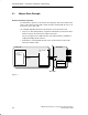
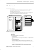
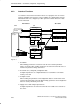
4.1.2 How an AS-i Slave Functions
Connecting to the AS-i Cable
The AS-i slave has an integrated circuit (AS-i chip; see also Section 3.2) that
provides the attachment of an AS-i device (sensor/actuator) to the common bus
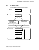
cable to the AS-i master. The integrated circuit contains the following components:
S 4 configurable data inputs and outputs
S 4 parameter outputs
The operating parameters, configuration data with I/O assignment, identification
code, and slave address are stored in additional memory (for example EEPROM).
I/O Data
The useful data for the automation components that were transferred from the AS-i
master to the AS-i slave are available at the data outputs. The values at the data
inputs are made available to the AS-i master when the AS-i slave is polled.
Parameter
Using the parameter outputs of the AS-i slave, the AS-i master can transfer values
that are not interpreted as simple data. These parameter values can be used to
control and switch over between internal operating modes of the sensors or
actuators. It could, for example, be possible to update a calibration value during
various operating phases. This function is possible with slaves with an integrated
AS-i connection providing they support the function in question.
Configuration
The input/output configuration (I/O configuration) indicates which data lines of the
AS-i slave are used as inputs, outputs or as bidirectional outputs. The I/O
configuration (4 bits) can be found in the description of the AS-i slave (an overview
of codings can be found in /1/).
In addition to the I/O configuration, the type of the AS-i slave is described by an
identification code, and with newer AS-Interface slaves by three identification
codes (ID code, ID1 code, ID2 code).
For more detailed information on the ID codes, refer to the manufacturer’s
description.