
Technical data

Further AS-i System Components
3-3
SIMATIC NET AS-Interface – Introduction and Basic Information
C79000-G8976-C089/03
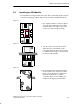
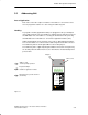
3.2 AS-i Modules: Blocks of the AS-i Slaves
Concept
Within the AS-i system, the AS-i modules can be compared with input and output
modules. Along with the actuators and sensors they make up the AS-i slaves and
connect the slaves to the AS-i master. The actuators/sensors are connected via
M12 connectors. The pinout corresponds to DIN IEC 947 5-2. The modules with
dimensions of approximately 45 x 45 x 80 mm are used locally on the machine
itself. They are connected via the AS-i cable and have the degree of protection
IP67.
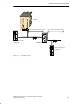
Active and Passive Modules
The following modules must be distinguished:
S The active AS-i module with integrated AS-i chip
Using this, conventional sensors and actuators can be connected. Every normal
actuator or sensor can therefore be networked via AS-i.
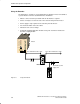
S The passive AS-i module
This does not contain its own electronics and allows the connection of AS-i
sensors and actuators with integrated AS-i chips.
In keeping with the concept of the standard AS-i master and the extended AS-i
master (see Section 1.2), either AS-i chips with standard functions or with
extended functions are used.
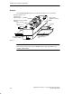
The modules are designed so that a uniform electromechanical interface to the
AS-i cable can be created. This is achieved with the uniform lower section of the
module, which is therefore also known as a coupling module.
Specially constructed upper module sections, also known as application modules
are also available. The variations in the module components range from the simple
cover for branching the AS-i cable to application modules with integrated AS-i
chips for connecting up to four conventional sensors or actuators.