
Technical data

AS-Interface (AS-i)
1-4
SIMATIC NET AS-Interface – Introduction and Basic Information
C79000-G8976-C089/03
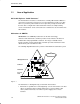
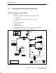
1.2 Overview of the AS-i System Components
System Components in the AS-i Network
S AS-i master
S AS-i slaves, distinguished according to their design as follows:
– AS-i modules
– Sensors/actuators with an integrated AS-i connection
S AS-i cable
S AS-i power supply unit
S Addressing unit
S SCOPE for AS-Interface
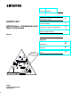
The following diagram illustrates how the described components can be
interconnected. The tree structure is particularly clear.
SIMATIC, e.g. CP 343-2
Branch
Branch M12
4O module with relay contacts
for connecting standard
actuators
4I module for
connecting standard
sensors
Standard 24V DC power
supply unit for external
supply to standard
actuators
Inductive BERO
with an integrated
AS-i connection
24 V DC
contactor
e.g. ind. BERO
Standard transmitter
e.g. position switch
Indicator
lamp
Solenoid valve
AS-i master AS-i power
supply unit
Sonar BERO with an
integrated AS-i connection
(slave 2)
(slave 1)
Button
(slave 3)
Standard sensor
(slave 4)
Shaped AS-i cable
Round AS-i cable
AS-i modules
with extended
addressing mode
A slave
B slave
Figure 1-2