Preface, Contents AS-Interface (AS-i) SIMATIC NET The AS-i Master AS-Interface – Introduction and Basic Information Further AS-i System Components The Master Mode – Commands, Sequence, Programming 1 2 3 4 Manual Appendix AS-Interface Industrial Ethernet PROFIBUS AS-Interface 12/99 C79000-G8976-C089 Release 03 References A Glossary B SIMATIC NET – Support and Training C
Safety Guidelines This manual contains notices which you should observe to ensure your own personal safety, as well as to protect the product and connected equipment. These notices are highlighted in the manual by a warning triangle and are marked as follows according to the level of danger: ! ! ! Danger indicates that death, severe personal injury or substantial property damage will result if proper precautions are not taken.
Preface Purpose of the Manual This manual contains basic information and an introduction to the AS-Interface system concept and the corresponding system components. You require this manual to understand the manuals that are shipped with the AS-i system components, particularly with the AS-i master. This release of the manual contains supplementary information relating to the expansion of the AS-i master specification and the extended SIMATIC NET product range.
Preface Other Documentation You should also read the product information bulletins supplied with the AS-i components from SIMATIC NET and the manuals that can be ordered additionally. Refer also to the references in the appendix of this manual.
Contents 1 2 3 4 AS-Interface (AS-i) . . . . . . . . . . . . . . . . . . . . . . . . . . . . . . . . . . . . . . . . . . . . . . . . . . . . . . 1-1 1.1 Area of Application . . . . . . . . . . . . . . . . . . . . . . . . . . . . . . . . . . . . . . . . . . . . . . 1-2 1.2 1.2.1 1.2.2 1.2.3 Overview of the AS-i System Components . . . . . . . . . . . . . . . . . . . . . . . . . . AS-i Masters . . . . . . . . . . . . . . . . . . . . . . . . . . . . . . . . . . . . . . . . . . . . . . . . . . . .
Contents A References . . . . . . . . . . . . . . . . . . . . . . . . . . . . . . . . . . . . . . . . . . . . . . . . . . . . . . . . . . . . . A-1 B Glossary . . . . . . . . . . . . . . . . . . . . . . . . . . . . . . . . . . . . . . . . . . . . . . . . . . . . . . . . . . . . . . . B-1 C SIMATIC NET – Support and Training . . . . . . . . . . . . . . . . . . . . . . . . . . . . . . . . . . . .
AS-Interface (AS-i) 1 This chapter deals with the following topics: S The range of applications that can be covered by the AS-Interface S Which system components are available on the AS-Interface S The system properties of the AS-Interface SIMATIC NET AS-Interface – Introduction and Basic Information C79000-G8976-C089/03 1-1
AS-Interface (AS-i) 1.1 Area of Application AS-i Cable Replaces “Cable Harnesses” The Actuator/Sensor Interface or AS-Interface, normally abbreviated to AS-i, is a connection system for the lowest process level in automation systems. The cable harnesses previously found at this level are replaced by a single electrical cable, the AS-i cable. Using the AS-i cable and the AS-i master, the simplest binary sensors and actuators can be connected to the control devices at the field level via AS-i modules.
AS-Interface (AS-i) S Simple and cost-effective wiring: simple installation with the “penetration” technique, high flexibility with tree-like wiring. S Fast reaction times: the AS-i master requires a maximum of 5 ms for cyclic data exchange with up to 31 nodes. S Nodes (AS-i slaves) on the AS-i cable can be either sensors/actuators with an integrated AS-i connector or AS-i modules to which up to four conventional binary sensors/actuators can be connected.
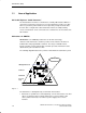
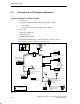
AS-Interface (AS-i) 1.2 Overview of the AS-i System Components System Components in the AS-i Network S AS-i master S AS-i slaves, distinguished according to their design as follows: – AS-i modules – Sensors/actuators with an integrated AS-i connection S AS-i cable S AS-i power supply unit S Addressing unit S SCOPE for AS-Interface The following diagram illustrates how the described components can be interconnected. The tree structure is particularly clear.
AS-Interface (AS-i) 1.2.1 AS-i Masters Siemens currently produces the following AS-i masters: S Standard AS-i Master Up to 31 standard slaves or slaves with the extended addressing mode (A slaves only) can be attached to standard AS-i masters.
AS-Interface (AS-i) for System Extended AS-i masters SIMATIC S7 PLC: CP 243-2 for S7-200 CP 343-2 for S7-300 Distributed I/Os: DP/AS-Interface Link 20E (type of protection IP 20) CP 343-2 for ET200M Note Since the range of available AS-i masters is constantly being extended, consult your Siemens representative about further AS-i masters. 1.2.2 AS-i Slaves All the nodes that can be addressed by an AS-i master are known as AS-i slaves.
AS-Interface (AS-i) Addressing Mode AS-i slaves are available with the following addressing modes: S Standard slaves Standard slaves each occupy one address on the AS-Interface. Up to 31 standard slaves can be connected to the AS-Interface. S Slaves with the extended addressing mode (A/B slaves) Slaves with the extended addressing mode can be operated in pairs at the same address with an extended AS-i master. This doubles the number of addressable AS-i slaves to 62.
AS-Interface (AS-i) 1.2.3 Further AS-i System Components AS-i Cable The AS-i cable, designed as an unshielded 2-wire cable, transfers signals and provides the power supply for the sensors and actuators connected using AS-i modules. Networking is not restricted to one type of cable. If necessary, appropriate modules or “T pieces” can be used to change to a simple 2-wire cable.
AS-Interface (AS-i) 1.3 System Characteristics and Important Data How the AS-Interface Functions The AS-Interface/AS-i system operates as outlined below: S Master-slave access techniques The AS-i interface is a “single master system”. This means that there is only one master per AS-i network which controls the data exchange. This polls all AS-i slaves one after the other and waits for a response. S Electronic address setting The address of an AS-i slave is its identifier.
AS-Interface (AS-i) space of approximately 2 cm3. S Increased functionality, more uses for the customer Direct integration allows devices to be equipped with a wide range of functions. Four data and four parameter lines are available. The resulting “intelligent” actuators/sensors increase the possibilities, for example, monitoring, parameter assignment, wear or pollution checks etc.
AS-Interface (AS-i) Special modules allow each of these bits to be used for a binary actuator or a binary sensor. This means that an AS-i cable with standard AS-i slaves can have a maximum of 248 binary attachments (124 inputs and 124 outputs). All typical actuators or sensors can be connected to the AS-interface in this way. The modules are used as distributed inputs/outputs.
AS-Interface (AS-i) 1-12 SIMATIC NET AS-Interface – Introduction and Basic Information C79000-G8976-C089/03
The AS-i Masters 2 AS-Interface is a single-master system. For SIMATIC systems, there are communications processors (CPs) that control the process or field communication as the AS-i masters. These also include gateways that operate like an AS-i master and allow access to the actuators and sensors, for example, of PROFIBUS DP. This chapter introduces you to these AS-i system components. For more detailed information on handling, configuring, and programming, refer to the manual of the relevant device.
The AS-i Masters 2.1 AS-i Masters for the SIMATIC S7-200 CP 242-2 (Standard AS-i Master) The CP 242-2 module allows the connection of an AS-i chain to the S7-200 programmable logic controller. The CP 242-2 provides the complete functionality of the AS-i master specification for standard AS-i masters (profile M1).
The AS-i Masters CP 242-8 (Standard AS-i Master) The CP 242-8 has not only the functions of the CP 242-2 but also a connection to PROFIBUS DP (DP slave). This allows the cost-effective connection of an S7-200 to PROFIBUS DP and the AS-Interface at the same time. Wider ranging network via PROFIBUS DP S7-200 CPU SIEMENS SF RUN STOP SIMATIC S7–200 I 0.0 I 0.1 I 0.2 I 0.3 I 0.4 I 0.5 I 0.6 I 0.7 Q0.0 Q0.1 Q0.2 Q0.3 Q0.4 Q0.
The AS-i Masters 2.2 AS-i Masters for the SIMATIC S7-300 CP 342-2 (Standard AS-i Master) The CP 342-2 is available as the standard AS-i master module for controllers of the S7-300 range and for the ET 200M distributed I/O system. The CP 342-2 occupies 16 input and 16 output bytes in the analog area of the controller via which the input data of the slaves can be read and the output data of the slaves can be set.
The AS-i Masters CP 343-2 (Extended AS-i Master) The CP 343-2 is an extended AS-i master for S7-300 series controllers and the ET 200 M distributed I/O system. The CP 343-2 occupies 16 input and 16 output bytes in the analog area of the controller via which the AS-i standard slaves and AS-i A slaves can be addressed. AS-i B slaves have an additional I/O area that is accessible using SFCs.
The AS-i Masters 2.3 AS-i Master for SIMATIC S5 PLCs in the Higher Performance Range CP 2430 (Standard AS-i Master) The CP 2430 is available as a master module (AS-i standard master) for programmable controllers of the S5-115U, S5-135U, S5-155U series. The CP 2430 is a double master that can operate two independent AS-i networks each with a maximum of 31 slaves. If required, the AS-i master can be used like an I/O module in the PLC to address the input and output data of the AS-i slaves.
The AS-i Masters 2.4 AS-i Master for SIMATIC S5 PLCs in the Lower Performance Range CP 2433 (Standard AS-i Master) The CP 2433 is available as a master module (AS-i standard master) for programmable controllers of the S5-90U, S5-95U, S5-100U series and the ET 200U distributed I/O system. The AS-i master is used like an I/O module in the PLC to address the input and output data of the AS-i slaves. In the address area of the PLC, it occupies 16 input bytes and 16 output bytes.
The AS-i Masters 2.5 AS-i Gateways DP / AS-i Gateway Even when using the PROFIBUS DP distributed I/Os, the use of AS-Interface can have advantages. The networking of the process peripherals can be extended beyond PROFIBUS to include the actuators/sensors.
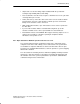
The AS-i Masters Wider ranging network via PROFIBUS DP DP/AS-Interface Link 20 E ADR BF 29 24 19 14 9 4 28 23 18 13 8 3 DIA SF DP-AS-Interface Link20 APF 27 22 17 12 7 2 31 26 21 16 11 6 1 CER AUP 30 25 20 15 10 5 0 CM X2 34 6GK714152AA0 Passive module (without integrated AS-i connection) Active module (with integrated AS-i connection) AS-i power supply Actuator/sensor (with integrated AS-i connection) AS-i cable Figure 2-6 AS-i distributor Example of a System Configuration with the DP/
The AS-i Masters 2.6 AS-i Master for ET 200X CP 142-2 (Standard AS-i Master) The CP 142-2 module (AS-i standard master) can be operated in the ET 200X distributed I/O system. It allows the connection of an AS-i chain to the I/O device. The special feature of the ET 200X distributed I/O system is its rugged construction complying with IP 65, IP 66 and IP 67.
The AS-i Masters 2.7 AS-i Master for PC-AT CP 2413 (Standard AS-i Master) The CP 2413 (AS-i standard master) allows the attachment of AS-Interface to PCs. The hardware of the AS-i master is implemented as a short PC-AT card. Up to four AS-i master CPs can be operated at the same time in one PC. This means that the Siemens AS-i PC master is also suitable for complex control tasks. The firmware running on the PC master is loaded when the host is started up.
The AS-i Masters Library for Integrating the AS-i Functions There are masters and libraries for C and Visual Basic applications for the master under MS-DOS and Windows. These functions are described in the “CP 2413 AS-i Master Module” manual.
Further AS-i System Components 3 As well as the AS-i masters described in this manual, the components of the AS-i transmission system and the AS-i slaves are also required on the AS-Interface. The following sections provide an overview of the basic characteristics and interaction of these components. Due to the continuing development of new AS-i system components, a complete presentation of all the currently available components is not possible.
Further AS-i System Components 3.1 The AS-i Cable Design and Advantages The AS-i cable (shaped cable) allows simple and fast installation of an AS-i system. The AS-i cable is a rubberized 2-wire cable (2 x 1.5 mm2). The profile section prevents stations being connected with incorrect polarity. The AS-i cable is contacted using the penetration technique. Contact blades penetrate the rubber jacket and make contact with the two wires.
Further AS-i System Components 3.2 AS-i Modules: Blocks of the AS-i Slaves Concept Within the AS-i system, the AS-i modules can be compared with input and output modules. Along with the actuators and sensors they make up the AS-i slaves and connect the slaves to the AS-i master. The actuators/sensors are connected via M12 connectors. The pinout corresponds to DIN IEC 947 5-2. The modules with dimensions of approximately 45 x 45 x 80 mm are used locally on the machine itself.
Further AS-i System Components Example: The following diagram illustrates an active AS-i module for four connections. Operating indicator of the actuator/sensor switching signal Upper section (application module) Application module operating indicator M12 connector for actuator/sensor lower section (coupling module) AS-i cable Standard rail 35 mm Figure 3-1 Note Please ask your local sales office or distributor about other AS-i modules (for example 4I/4O module).
Further AS-i System Components 3.3 Installing an AS-i Module The installation of an AS-i module on the AS-i cable is particularly simple using the connection technique described. This is made clear by the following illustration: Figure 3-2 1. The coupling module is screwed or clipped onto a 35 mm standard rail. The coupling module includes four stoppers. These are used to close unused cable openings. Figure 3-3 2. The AS-i cable is inserted.
Further AS-i System Components 3.4 AS-Interface Repeater / Extender Area of Application The AS interface repeater and extender is intended for use in an actuator-sensor interface environment. The device is used to extend the maximum possible length of the AS-interface of 100 m. An existing 100 m segment can be extended by a maximum of two further 100 m segments. Using the Repeater The AS-interface repeater is used when slaves must be operated on all cable segments.
Further AS-i System Components ACTIVESLAVES CP FAULT RUN S1 POWER FAIL 30 20 10 Master CONFIGERROR AUTOPROG CONFIGMODE SETCONFIG CHANGEMODE CP 2433 SINICS1 6GK1243–3SA00 1 2 34 5 6 S II M I N 9 8 7 6 5 4 3 2 1 0 7 9 + 8 10 max. 100 m AS-Interface cable max.
Further AS-i System Components Using the Extender The AS-Interface extender is used in applications in which the master is installed at a greater distance from the actual AS-Interface installation: S Masters can be located up to 100 m from the AS-interface segment. S Slaves can only be used on the side of the extender away from the master. S Power supply is only required on the side away from the master. S No electrical isolation of the two cables. S Indication of the correct voltage.
Further AS-i System Components 3.5 Addressing Unit Area of Application Each slave on the AS-i requires an address. This address is saved on the slave. You can program the address of a slave using the addressing unit. Handling To program a module (application module), it is plugged in to the special adapter on the addressing unit. The stored address is displayed on the unit when you press the ADR button. The new address is set using the arrow buttons.
Further AS-i System Components 3.6 SCOPE Diagnostic Software for AS-Interface Area of Application The SCOPE diagnostic software for the AS-Interface is a monitoring program capable of recording and evaluating the data exchange in AS-i networks during installation and operation. SCOPE for AS-interface can be operated on a PC under WINDOWS in conjunction with the AS-i master communications processor CP 2413. The software is operated using the known WINDOWS conventions.
The Master Mode – Commands, Sequence, Programming 4 The tasks and functions of an AS-i master are described below. This section is important for understanding the functions, modes and interfaces available with the AS-i master modules. These functions and interfaces are described in detail in the manuals of the individual CPs.
The Master Mode – Commands, Sequence, Programming 4.1 Master-Slave Principle How the AS-Interface Operates The AS-Interface operates on the master-slave principle. This means that the AS-i master connected to the AS-i cable controls the data exchange with the slaves via the interface to the AS-i cable. The following diagram illustrates the two interfaces of the AS-i master CP. S The process data and parameter assignment commands are transferred via the interface between the master CPU and the master CP.
The Master Mode – Commands, Sequence, Programming 4.1.1 Tasks and Functions of the AS-i Master Graded Range of Performance – Use of Profiles According to the AS-i Specification The AS-i master specification distinguishes masters with different ranges of functions known as a “profile”. For standard AS-i masters and extended AS-i masters there are three different master classes (M0, M1, M2 for standard masters, M0e, M1e, M2e for extended masters).
The Master Mode – Commands, Sequence, Programming 4.1.2 How an AS-i Slave Functions Connecting to the AS-i Cable The AS-i slave has an integrated circuit (AS-i chip; see also Section 3.2) that provides the attachment of an AS-i device (sensor/actuator) to the common bus cable to the AS-i master.
The Master Mode – Commands, Sequence, Programming 4.2 Data Transfer Information/Data Structure Before introducing you to the operating phases and the functions during these operating phases, a brief outline of the information structure of the AS-i master/slave system is necessary. In the following diagram, the data fields and lists of the system are configured in the system structure diagram you saw in the previous section.
The Master Mode – Commands, Sequence, Programming – The list of activated AS-i slaves (LAS) The LAS specifies which AS-i slaves were activated by the AS-i master. I/O data are only exchanged with activated AS-i slaves. S I/O data The process input and output data. S Configuration data These are non-volatile data (e.g. stored in an EEPROM), which are available unchanged even following a power failure.
The Master Mode – Commands, Sequence, Programming 4.2.1 The Operating Phases The following diagram illustrates the individual operating phases.
The Master Mode – Commands, Sequence, Programming Initialization mode The initialization mode, also known as the offline phase, sets the basic status of the master. The module is initialized after switching on the power supply or following a restart during operation. During the initialization, the images of all the slave inputs and the output data from the point of view of the application are set to the value “0” (inactive).
The Master Mode – Commands, Sequence, Programming data). If an error is detected during the transmission, the master repeats the appropriate poll. – Management phase During this phase, all existing jobs of the control application are processed and sent. Possible jobs are, for example, as follows: Parameter transfer: Four parameter bits (three parameter bits with AS-i slaves with the extended addressing mode) are transferred to a slave and are used, for example, for a threshold value setting.
The Master Mode – Commands, Sequence, Programming 4.2.2 Interface Functions To control the master/slave interaction from the user program, there are various functions available on the interface. The possibilities are explained based on the illustration below. Here, simply the possible operations and the direction of data flow are illustrated. AS-i master AS-i slave CPU CP Data images Process image I/O data User program I/O data I/O data Act. params. 1. read/write Parameter s Act.
The Master Mode – Commands, Sequence, Programming 4.2.3 Operating Extended AS-i Slaves with Standard AS-i Masters Note Please note the following information about operating extended AS-i slaves with standard AS-i masters! S If A slaves are connected to standard masters, make sure that the most significant slave bit (bit 4) of each A slave is set to “0”. The most significant parameter bit (bit 4) must also be set to “1” (default value).
The Master Mode – Commands, Sequence, Programming 4-12 SIMATIC NET AS-Interface – Introduction and Basic Information C79000-G8976-C089/03
References A /1/ AS-Interface Das Aktuator-Sensor-Interface für die Automation Werner Kriesel, O.W. Madelung, Carl Hanser Verlag München Wien 1994 /2/ AS-Interface Complete Specification can be ordered from the AS-i Association e.V. Address: AS-International Association e.V. Geschäftsführung: Dr. Otto W. Madelung Auf den Broich 4A D – 51519 Odenthal Germany Tel.: +49 – 2174 – 40756 Fax.: +49 – 2174 – 41571 (The AS-i technology is promoted by the AS-Interface Association e. V.
References /5/ SIMATIC NET Industrial Communications Networks PROFIBUS Networks Manual Siemens AG /6/ PROFIBUS standard EN 50170 Order numbers The order numbers of the SIEMENS documentation listed above can be found in the catalogs “SIMATIC NET Industrial Communication, Catalog IK10” and “SIMATIC Programmable Controllers SIMATIC S7 / M7 / C7”. You can order these catalogs and obtain additional information from your local SIEMENS branch or distributor.
Glossary B APF AS-i Power Fail. Flag or LED display that indicates that the power supply on the AS-i cable is too low or has failed (for example failure of the AS-i power supply unit). AS-i (AS-Interface) Actuator-sensor interface. A network system for the lowest field area of the automation range. It is suitable for networking sensors and actuators with control devices. (previously: SINEC S1) AS-i A/B slave AS-i A/B slaves use the extended addressing mode.
Glossary AS-i module For the AS-Interface, a module concept has been defined that allows the blocklike linking of AS-i slaves – sensors and actuators – via AS-i modules. The following types of module exist: The active AS-i module with an integrated AS-i chip; using this, up to four conventional sensors and actuators can be connected. The passive AS-i module; this functions as a distributor and provides a connection for up to four sensors and actuators with an integrated AS-i chip.
Glossary Nibble A nibble is a unit of information consisting of four bits. Standard AS-i master Up to 31 standard slaves or slaves with the extended addressing mode (A slaves only) can be attached to a standard AS-i master.
Glossary B-4 SIMATIC NET AS-Interface – Introduction and Basic Information C79000-G8976-C089/03
C SIMATIC NET – Support and Training SIMATIC Training Center To help you to become familiar with the SIMATIC S7 automation system, we offer a range of courses. Please contact your regional training center or the central training center in D 90327 Nuremberg, Germany. Infoline: Tel. 0180 523 5611 (48 Pfg./min), Fax. 0180 523 5612 Internet: http://www.ad.siemens.de/training E-mail: AD-Training@nbgm.siemens.
SIMATIC NET – Support and Training SIMATIC Premium Hotline (Calls charged, only with SIMATIC Card) Time:Mo.-Fr. 0:00 to 24:00 Phone: +49 (911) 895-7777 Fax: +49 (911) 895-7001 SIMATIC Customer Support Online Services The SIMATIC customer support team provides you with comprehensive additional information on SIMATIC products in its online services: S You can obtain general current information: – On the Internet at http://www.ad.siemens.de/net – Using fax polling no.
Numbers 2-wire cable, 1-9, 3-2 A A/B slaves, 1-7 Activation phase, 4-8 in the configuration mode, 4-7 in the protected mode, 4-7 Address setting, electronic, 1-9 Addressing mode, 1-5, 1-10 slaves with extended addressing mode, 1-7 Addressing unit, 1-8, 3-9 Analog value transfer, 1-5 AS-i cable, 1-2, 1-4, 1-8, 3-2 AS-i master, 1-4, 2-2 extended, 1-5 Siemens products, 1-5 standard, 1-5 tasks and functions, 4-3 AS-i master specification, 1-11 AS-i module, 1-6, 3-5 meaning and function, 3-3 AS-i power supply u
Master-slave access techniques, 1-9 Master-slave principle, 4-2 R Normal mode, 4-8 Range of functions, of the master modules, 1-11 Read and store (configured) configuration data, 4-10 Repeater / extender, 3-6 O S Offline phase, 4-8 Operating phases, 4-7 Operating reliability and flexibility, 1-9 SCOPE for AS-Interface, 1-4, 1-8 SCOPE S1, 1-8 Sensors/actuators, with integrated AS-i connection, 1-6 Slave addresses, changing, 4-9 Standard rail, 3-5 Startup phase, 4-8 System characteristics, 1-9 System c
Siemens AG A&D PT2 Östliche Rheinbrückenstr.
Remarks Form Your comments and recommendations will help us to improve the quality and usefulness of our publications. Please take the first available opportunity to fill out this questionnaire and return it to Siemens. Please give each of the following questions your own personal mark within the range from 1 (very good) to 5 (poor). 1. Do the contents meet your requirements? 2. Is the information you need easy to find? 3. Is the text easy to understand? 4.