
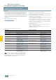
Specifications

AS-Interface Slaves
I/O modules for operation in the field
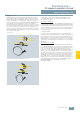
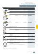
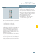
Digital I/O modules IP67 - K20
6/93
Siemens IK PI · 2009
6
■
Design (continued)
Please note the following boundary conditions:
• The configuration guidelines for AS-Interface apply. For all
M12 connecting cables the maximum permissible current is
limited to 4 A. The cross-section of these cables amounts to
just 0.34 mm². For connection of the K20 modules, the afore-
mentioned M12 connecting cables can be used for the spur
lines. The voltage drop caused by the ohmic resistance
(approx. 0.11 Ω/m) must be taken into account.
• For round cable connections with shared AS-i and U
aux
in a
single cable, the following maximum lengths apply:
- per spur line from feeder to module: maximum 5 m
- total of all round cable segments in an AS-Interface network:
maximum 20 m
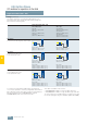
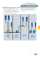
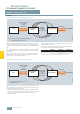
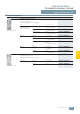
Connection examples for K20 modules
≤ 5 m
≤ 5 m
≤ 1,5 m
NSA0_00451a
Connection using
4-fold M12 feeder
(3RK1 901-1NR00)
(AS-i/U
aux
)
for I/O modules
Connection using
M12 feeder
(3RK1 901-1NR2.)
(AS-i/U
aux
)
for I/O modules
Connection using
M12 feeder
(3RK1 901-1NR1.)
(AS-i without U
aux
)
for modules with inputs
Further distribution
using MT-12 T feeder
(3RK1 901-1TR00)