
Specifications

AS-Interface Slaves
I/O modules for operation in the field
Digital I/O modules IP67 - K20
6/90
Siemens IK PI · 2009
6
■
Overview
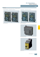
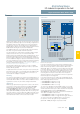
Use in tight spaces
The K20 compact module range rounds off the AS-Interface
compact modules with a particularly slim design and a width of
a mere 20 mm. Thanks to its extremely compact dimensions,
these modules are particularly suited for handling machine ap-
plications in the field of production engineering where modules
need to be arranged in the smallest of spaces.
Robotics is yet another application area. Instead of the AS-Inter-
face flat cable, the K20 modules are connected to AS-Interface
over a round cable with M12 cable box.
The AS-Interface bus cable and the 24 V DC auxiliary power
supply are routed in this case in a shared round cable. This
enables extremely compact installation.
The flexibility of the round cable means that it can also be
used on moving machine parts without any problems. The
K20 modules are also ideal for such applications as their non-
encapsulated design makes them particularly light in weight.
In applications with tow chains, many users rely on placing
the AS-Interface bus cable in a round cable. In this case, the
K20 modules support direct connection to the round cable. No
flat to round cable adapter is required.
The K20 compact module range includes standard AS-Interface
modules, as well as an ASIsafe version for the connection of fail-
safe sensors, such as EMERGENCY STOP pushbuttons or pro-
tective door monitoring. All standard AS-Interface K20 modules
support, as far as technically possible, the expanded address
mode (A/B addresses) according to AS-Interface specification
2.1, which enables connection of 62 stations to an AS-Interface
network. The K20 module with four inputs and four outputs works
in expanded address mode according to AS-Interface specifica-
tion 3.0 which, for the first time, supports four outputs with an
A/B slave, thus enabling 248 inputs and 248 outputs in a fully
expanded AS-Interface network.
For particularly space-saving dimensions, the sensors and actu-
ators are connected over M8 plug-in connectors. Alternatively,
M12 connectors with Y assignment can be used.
■
Design
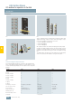
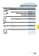
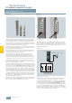
Mounting
Mounting the K20 modules: On the front (see left) or on the side
(see right)
The K20 modules are mounted with two screws. No mounting
plate is required. The modules can be mounted either on the
front or the side. This flexibility allows users to place them where
they will be best protected and save the most space, e. g. on
standard mounting rails.
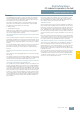
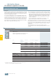
Addressing
Addressing the K20 modules
Addressing the K20 modules is performed using the same
socket as for the bus connection. The module is connected
to the 3RK1 904-2AB01 addressing unit using a standard M12
connecting cable (2- or 3-pole), e. g. 3RX8 000-0GF32-1AB5.
If the older version of the 3RK1 904-2AB00 addressing unit is
used, a special addressing cable (3RK1 901-3RA00) is required
for connecting to the addressing unit. When the addressing
operation is completed, the addressing cable is removed again
and the module connected to the bus cable. Never use a 4-pole
or 5-pole connecting cable for the addressing.
NSA0_00443a
3RK1 904-2AB01
AS-Interface: 1 ... 31 (1A ... 31B)
ASi-
3
3RX8 000-0GF32-1AA6
3RX8 000-0GF32-1AB0
3RX8 000-0GF32-1AB5
ASi-
3
ASi+
1
4
ASi+
1
32
41