
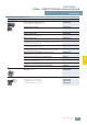
Specifications

AS-Interface
ASIsafe — SIMATIC FS400 light curtains and light grids
3RG78 43 series, Internal evaluation, Type 2
Standard Function package, Transistor output
6/54
Siemens IK PI · 2009
6
■
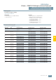
Technical specifications
1)
The circuits connected to the inputs and outputs must comply with the
air gaps and creepage distances specified in the applicable standards
for safe isolation.
Transistor outputs receiver
1)
If an error occurs (when disconnecting the GND line), the output acts like a
120 kΩ resistance to UV. A downstream safety PLC may not identify this as
a logical "1".
2)
Please note further constraints due to cable length and load current.
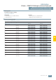
Type 3RG78 43
Safety category EN IEC 61496;
SIL2 to IEC 61508
Typ 2
Detection capability (resolution)
20 mm, 30 mm, 40 mm, 90 mm
Protective field width, range
• for 20 mm resolution 0.5 ... 15 m
• for 30 mm resolution
0 ... 8 m
• for 40 mm resolution
0.8 ... 20 m
• for 90 mm resolution
0.8 ... 20 m
Supply voltage U
V
(emitter and receiver)
24 V DC ± 20 %
(external power pack with
safe isolation and compensation
of 20 ms voltage dip is necessary,
min. 1 A current reserve)
Residual ripple of supply voltage
± 5 % within the limits of U
V
Current consumption
• Emitter 45 mA
• Receiver
140 mA (without external load)
General value for external fuse
in the transmitter and receiver
supply leads
1 A
Permissible conductor
cross-section
• Emitter 0.25 mm
2
• Receiver 0.14 mm
2
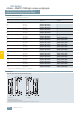
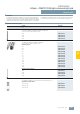
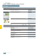
Type 3RG78 43
Emitter
Light-emitting diodes according to
EN 60825-1:1994+
A1:2002+A:2001
• Class
1
• Wave length
950 nm
• Pulse duration
7 µs
• Pulse interval
3.1 ms
• Power
< 10 µW
Synchronization
Optically between emitter
and receiver
Test repeat time for
integrated cyclical test
100 ms
Safety class (VDE 106)
III
1)
Ambient temperature
• Operation 0 ... +50 °C
• Storage
–25 ... +70 °C
Relative humidity
15 ... 95 %
Degree of protection
IP65
Signal inputs
• Emitter test input Input: Contact or transistor
connected to +24 V DC,
current load: 20 mA max.
• Receiver signal input BA1
Input: Contact or transistor
connected to +24 V DC,
or connect to GND,
current load: 10 mA max.
• Receiver signal input BA2
Input: Contact or transistor
connected to +24 V DC,
or connect to GND,
current load: 10 mA max.
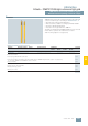
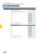
OSSD transistor outputs 2 pnp safety-related transistor outputs, short-circuit-proof
minimal typisch maximal
Operational voltage active high
U
V
- 1.9 V U
V
- 1 V U
V
- 0.8 V
Operational voltage, low
– 200 mV + 1 V
Operational current
– – 250 mA
Leakage current
– < 2 µA
1)
–
Load capacitance
– – < 2.2 µF
Load inductance
– – 2.0 H
Permissible line resistance to load
– – < 50 Ω
2)
Permissible conductor
cross-section: Receiver
– – 0.14 mm
2
Permissible cable lengths
between receiver and load
– – 100 m
Auxiliary pulse width
20 µs – 230 µs
Auxiliary pulse interval
3.7 ms – 46 ms
OSSD reactivation time after
beam interruption (without RES)
– 100 ms –
OSSD response time
Depending on number of beams, see operating instructions