
Specifications
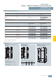


AS-Interface
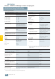
ASIsafe — SIMATIC FS400 light curtains and light grids
3RG78 46 series, Internal evaluation, Type 4
Standard function package, transistor output
6/50
Siemens IK PI · 2009
6
■
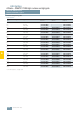
Technical specifications
1)
The circuits connected to the inputs and outputs must comply with the
air gaps and creepage distances specified in the applicable standards
for safe isolation.
1)
Fast recovery voltage for contactors, otherwise 0 V
2)
Please note further constraints due to cable length and load current.
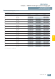
Type 3RG78 46
Safety category IEC/EN 61496
Type 4
Detection capability (resolution)
14 mm, 20 mm, 30 mm,
40 mm, 90 mm
Protective field width, range
• 14 mm resolution 0.5 ... 5 m
• 20 mm resolution
0.7 ... 14 m
• 30 mm resolution
0.5 ... 9 m
• 40 mm resolution
0.9 ... 20 m
• 90 mm resolution
0.9 ... 20 m
Supply voltage U
v
(emitter and receiver)
24 V DC ± 20 %
(external power pack with safe
isolation and compensation of
20 ms voltage dip is necessary,
minimum 1 A current reserve)
Residual ripple of supply voltage
± 5 % within the limits of U
v
Current consumption
• Emitter 75 mA
• Receiver
110 mA (without external load)
General value for external fuse in
the transmitter and receiver supply
leads
1 A medium time-lag
Permissible conductor cross-sec-
tion
• Emitter 0.25 mm
2
• Emitter 0.14 mm
2
Emitter Light-emitting diodes according to
EN 60825-1:1994+
A1:2002+A:2001
• Class
1
• Wave length
950 nm
• Power
< 50 µW
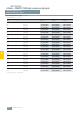
Type 3RG78 46
Synchronization
Optically between emitter
and receiver
Safety class (VDE 106)
1)
III
Ambient temperature
• Operation 0 ... +55 °C
• Storage
–25 ... +70 °C
Relative humidity
15 ... 95 %
Degree of protection
IP65
Signal inputs
• Emitter pin 4
- test input • Input: Contact or transistor
connected to +24 V DC
• 0 V or spare = Test
• Current load: 20 mA max.
• Receiver pin 1
- start/restart key Input: Contact (NO) connected to
24 V DC, current load: 15 mA max.
- error/pollution group alarm
Output: pnp: Connected to
24 V DC , 80 mA max.
• Receiver pin 3
- EDM (contactor control) • Input: Contact (NC) connected to
0 V
• Current load: 15 mA max
- without EDM
24 V DC connection
• Receiver pin 4
-with RES Input: 24 V DC
- without RES
Jumper to pin 1
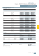
OSSD transistor outputs 2 pnp safety-related transistor outputs, cross-connection monitored, short-circuit-proof
Minimum Typical Maximum
Operational voltage active high
(U
v
– 1.6 V)
For resistive load I
rated
= 250 mA
– +22 V –
Operational voltage, low
-80 V
1)
0 V + 2,8 V
Operational current
– 250 mA –
Leakage current
– < 5 µA < 20 µA
Load capacitance
– – < 220 nF
Load inductance
– – < 2,0 H
Permissible line resistance to load
– – < 300 Ω
2)
Permissible line length between
receiver and load (with 0.25 mm
2
)
– – 100 m
Test pulse width
30 µs – 100 µs
Test pulse space
– – 22 µs
OSSD reactivation time after beam
interruption (without RES)
40 ms 100 ms –
OSSD response time
Depending on number of beams, see operating instructions