
Specifications

AS-Interface Slaves
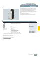
3SF5 Pushbutton Units and Indicator Lights
AS-Interface enclosures with standard fittings
6/137
Siemens IK PI · 2009
6
■
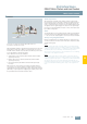
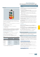
Overview
Enclosures with standard fittings are available with:
7 1 to 3 command positions
7 Operational voltage through AS-Interface (approx. 30 V),
7 Vertical mounting type
7 Plastic enclosures are equipped with plastic actuators and in-
dicators, metal enclosures are equipped with metal actuators
and indicators.
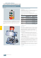
The actuators/indicators are fixed with an enclosure nut. If re-
quired it can be disassembled with a 27 mm socket wrench or
with a 3SX17 07 ring nut wrench.
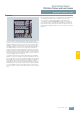
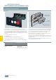
The enclosures without EMERGENCY STOP each have one user
module with 4I/3O; the enclosures with EMERGENCY STOP
have a safe AS-Interface slave integrated in the enclosure.
EMERGENCY STOP enclosures are fitted with two NC contact
blocks, which are wired to the safe slave. The contact blocks
and lampholders (with spring-loaded terminals) of the control
device, and the AS-Interface slaves, are mounted in the base of
the enclosure and are cable-connected.
The plastic versions of the enclosures have a connection for the
AS-Interface flat cable (the cable is routed past the enclosure on
the outside); in the case of the metal versions the AS-Interface
cable is routed into the enclosure.
The metal versions of the EMERGENCY STOP enclosures can
also be supplied with an M12 plug in place of the gland.
■
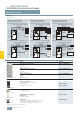
Selection and ordering data
Version Order No.
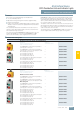
AS-Interface enclosures, plastic, with standard fittings
3SF5 811-0AA08
3SF5 812-0DA00
Equipment
(A, B, C = identification letters
of the command positions)
Number of
command positions
A = EMERGENCY STOP mushroom pushbutton,
yellow top part of enclosure
1 3SF5 811-0AA08
A = EMERGENCY STOP mushroom pushbutton,
yellow top part of enclosure, with protective collar
1
3SF5 811-0AB08
B = Pushbutton green, label "I"
A = Pushbutton red, label "O"
2
3SF5 812-0DA00
B = Pushbutton white, label "I"
A = Pushbutton black, label "O"
2
3SF5 812-0DB00
C = Indicator light clear, label without inscription
B = Pushbutton green, label "I"
A = Pushbutton red, label "O"
3
3SF5 813-0DA00
C = Indicator light clear, label without inscription,
B = Pushbutton white, label "I"
A = Pushbutton black, label "O"
3
3SF5 813-0DC00
C = Pushbutton black, label "II"
B = Pushbutton black, label "I"
A = Pushbutton red, label "O"
3
3SF5 813-0DB00
3SF5 811-2AB08
3SF5 812-2DA00
3SF5 813-2DA00
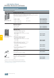
AS-Interface enclosures, metal, with standard fittings
Equipment
(A, B, C = identification letters
of the command positions)
Number of
command positions
With M12 connector socket
A = EMERGENCY STOP mushroom pushbutton,
yellow top part of enclosure
1 3SF5 811-2AA10
A = EMERGENCY STOP mushroom pushbutton,
yellow top part of enclosure, with protective collar
1
3SF5 811-2AB10
With cable gland
A = EMERGENCY STOP mushroom pushbutton,
yellow top part of enclosure
1 3SF5 811-2AA08
A = EMERGENCY STOP mushroom pushbutton,
yellow top part of enclosure, with protective collar
1
3SF5 811-2AB08
B = Pushbutton green, label "I"
A = Pushbutton red, label "O"
2
3SF5 812-2DA00
B = Pushbutton white, label "I"
A = Pushbutton black, label "O"
2
3SF5 812-2DB00
C = Indicator light clear, label without inscription
B = Pushbutton green, label "I"
A = Pushbutton red, label "O"
3
3SF5 813-2DA00
C = Indicator light clear, label without inscription,
B = Pushbutton white, label "I"
A = Pushbutton black, label "O"
3
3SF5 813-2DC00
C = Pushbutton black, label "II"
B = Pushbutton black, label "I"
A = Pushbutton red, label "O"
3
3SF5 813-2DB00