
Specifications


AS-Interface Slaves
Modules with special functions
Modules with special functions
Overvoltage protection module
6/110
Siemens IK PI · 2009
6
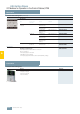
Configuration guidelines
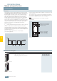
Configuration guidelines for overvoltage protection module
The grounding of protection modules and the units to be pro-
tected must be effected through a shared grounding point
(equipotential bonding). If insulated devices are protected,
their mounts must be included in the grounding points.
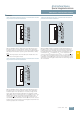
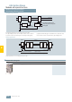
Sample application
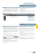
Sample application for overvoltage protection module
■
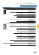
Selection and ordering data
AS-
Inter-
face
AS-
Inter-
face
NSA0_00093a
OVP = Overvoltage protection
Mounting plate
Application
Device with
ground terminal
Device without ground terminal
→ Grounding of the mounting plate
Application
OVP
NSA0_00092a
AS-
Inter-
face
A B
AS-
Inter-
face
AS-
Inter-
face
AS-
Inter-
face
OVP = Overvoltage protection
OVP OVP
protected range
Zone 1 Zone 1 Zone 2
Protection approx. 5m to the right
Equipotential bonding
(system earth)
Protection approx. 0.5m to the left
Version Order No.
3RK1 901-1GA00
Overvoltage protection module 3RK1 901-1GA00