AS-Interface 6/2 6/2 6/3 6/4 6/5 Introduction Transmission technology Configuration examples Communications overview AS-Interface specification 6/7 6/7 6/8 6/12 6/15 6/16 6/18 6/20 ASIsafe Introduction AS-Interface safety monitors AS-Interface safety modules 3SF1 Position Switches – Plastic enclosures – Metal enclosures 3SF1 Position Switches with Separate Actuator – Plastic enclosures – Metal enclosures 3SF1 Position Switches with Tumbler – Plastic enclosures – Metal enclosures 3SF1 hinge switches – Pla
AS-Interface Introduction Transmission technology ■ Overview AS-Interface The AS-Interface is an open, international standard in accordance with EN 50295 and IEC 62026-2 for fieldbus communication. Leading manufacturers of actuators and sensors worldwide support AS-Interface. The electrical and mechanical specifications of the AS-Interface Association are made open to interested companies. The AS-Interface is a single master system.
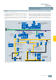
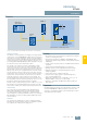
AS-Interface Introduction Configuration examples ■ Design Process or field communication AS-Interface is used wherever individual actuators and sensors are distributed throughout the machine (e.g. in a bottling plant or production line, etc.). AS-Interface replaces complex cable trees and connects binary and analog actuators and sensors such as proximity switches, valves or LEDs to a programmable controller such as SIMATIC or a PC.
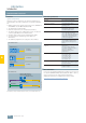
AS-Interface Introduction Communications overview ■ Overview ■ Technical specifications System components Standard EN 50295 / IEC 61158 Numerous system components are offered to implement the communication.
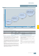
AS-Interface AS-Interface specification ■ Overview Speed/Flexibility • 4DI/4DO in A/B technology • 8DI/8DO in A/B technology • Additional analog profiles • Transmission of serial data • Safety monitor • Safe input slaves ASi Spec. V3.0 • • • ASIsafe 31 Slaves ASi Spec. V2.1 5 ms bus cycle time NSA0_00453a • • 62 Slaves (10 ms) Analog profiles Diagnostics peripherals ASi Spec. V2.
AS-Interface AS-Interface specification ■ Overview (continued) AS-Interface master To be able to operate A/B slaves on an AS-Interface network you must also use master modules that meet the minimum requirements of Specification 2.1. A/B technology is supported by the masters of the SIMATIC S7 and the DP/AS-Interface links from Siemens. Only standard slaves and A slaves (= A/B slave with an A address) can be operated on masters which do not support Specification 2.1.
AS-Interface ASIsafe Introduction ■ Overview Power supply unit AS-i POWER Standard PLC Standard-Master Safety monitor StandardSlave AS-Interface Safe slave with EMERGENCY STOP Signal evaluation of slave/safety monitor Secure communication and standard communication on AS-Interface Safety is included The ASIsafe concept supports the integration of safety-related components, such as EMERGENCY STOP switches, protective door switches or safety light arrays, directly in the AS-Interface network.
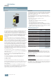
AS-Interface ASIsafe AS-Interface safety monitors ■ Overview ■ Application The safety monitor acts as a "bus-based safety relay". It provides a user-friendly introduction to safety-orientated communication over fieldbuses thanks to its simple configuration using the graphic PC software asimon. The standard infrastructure of the AS-i network (AS-i master under standard PLC, AS-i power supply unit) can still be used without restriction.
AS-Interface ASIsafe AS-Interface safety monitors ■ Application (continued) Features of the basic safety monitor • Wildcards and deactivating of monitoring modules Wildcards are available for the configuration. These wildcards are integrated in the configuration and diagnostics and can be activated very easily if required. User-friendly and easy configuring is thus possible even when system configurations change.
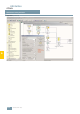
AS-Interface ASIsafe AS-Interface safety monitors ■ Application (continued) 6 Interface of the configuration software asimon V3 6/10 Siemens IK PI · 2009
AS-Interface ASIsafe AS-Interface safety monitors ■ Selection and ordering data 3RK1 105-1BE04-0CA0 Version Order No.
AS-Interface ASIsafe AS-Interface safety modules ■ Overview Following modules are available for selection: K20F compact safety modules for operation in the field Being only 20 mm wide, the K20F module is particularly well suited for applications where modules need to be arranged in the most confined space. The K20F modules are connected to the AS-Interface with a round cable with M12 cable box instead of with the AS-Interface flat cable. This enables extremely compact installation.
AS-Interface ASIsafe AS-Interface safety modules ■ Selection and ordering data Version Order No.
AS-Interface ASIsafe AS-Interface safety modules ■ Selection and ordering data (continued) Version Order No.
AS-Interface ASIsafe 3SF1 Position Switches ■ Overview The 3SF1 position switches with safety-oriented communication can be directly connected using the AS-Interface bus system. The safety functions no longer have to be conventionally wired up. With the 3SF1 position switches the ASIsafe electronics are integrated in the switch enclosure.
AS-Interface ASIsafe 3SF1 position switches Plastic enclosures ■ Selection and ordering data Modular system For the ASIsafe version of the position switch, the basic switch and actuator must be ordered separately. 1 or 2 contacts · 3 LEDs · Degree of protection IP65 (31 mm) or IP66/IP67 (50 mm) · M12 connector socket Version Contacts LEDs Order No.
AS-Interface ASIsafe 3SF1 position switches Plastic enclosures ■ Selection and ordering data (continued) Version Diameter Order No.
AS-Interface ASIsafe 3SF1 position switches Metal enclosures ■ Selection and ordering data Modular system For the ASIsafe version of the position switch, the basic switch and actuator must be ordered separately. 1 or 2 contacts · 3 LEDs · Degree of protection IP66/IP67 · M12 connector socket Version Contacts LEDs Order No.
AS-Interface ASIsafe 3SF1 position switches Metal enclosures ■ Selection and ordering data (continued) Version Diameter Order No.
AS-Interface ASIsafe 3SF1 Position Switches with Separate Actuator ■ Overview ■ Benefits The 3SF1 position switches with safety-oriented communication can be directly connected using the AS-Interface bus system. The safety functions no longer have to be conventionally wired up. With the 3SF1 position switches the ASIsafe electronics are integrated in the switch enclosure.
AS-Interface ASIsafe 3SF1 position switches with separate actuator Plastic enclosures ■ Overview • Contacts: 1 or 2 slow-action contacts • Status display with 3 LEDs 24 V DC; 1: F–IN1, 2: F–IN2, 3: AS-i/FAULT • Degree of protection IP65 (31 mm) or IP66/IP67 (50 mm) ■ Selection and ordering data Version1) Contacts Order No.
AS-Interface ASIsafe 3SF1 position switches with separate actuator Metal enclosures ■ Overview • Contacts: 1 or 2 slow-action contacts • Status display with 3 LEDs 24 V DC; 1: F–IN1, 2: F–IN2, 3: AS-i/FAULT • Degree of protection IP66/IP67 ■ Selection and ordering data Version1) Contacts Order No.
AS-Interface ASIsafe 3SF1 Position Switches with Tumbler ■ Overview The 3SF1 position switches with safety-oriented communication can be directly connected using the AS-Interface bus system. The safety functions no longer have to be conventionally wired up. With the 3SF1 position switches the ASIsafe electronics are integrated in the switch enclosure.
AS-Interface ASIsafe 3SF1 position switches with tumbler Plastic enclosures ■ Overview 5 directions of approach · Degree of protection IP66/IP67 • Contacts, slow-action contacts: - Version -1BA1: ASIsafe channel 1 on 1 NC contact from the actuator and channel 2 on 1 NC contact from the magnet - Version -1BA3: ASIsafe channel 1 on 1 NC contact from the actuator and channel 2 on 1 NC contact from the actuator • Magnet: Rated operational voltage 24 V DC • Locking force 1300 N (1000 N according to GS-ET 19)
AS-Interface ASIsafe 3SF1 position switches with tumbler Metal enclosures ■ Overview 5 directions of approach · Degree of protection IP66/IP67 • Contacts, slow-action contacts: ASIsafe channel 1 on 1 NC contact from the actuator and channel 2 on 1 NC contact from the magnet • Magnet: Rated operational voltage 24 V DC • Locking force 2600 N (2000 N according to GS-ET 19) • Status display with 4 LEDs 24 V DC; 1: F–IN1, 2: F–IN2, 3: AS-i, 4: FAULT ■ Selection and ordering data Tumbler1) Contacts Order N
AS-Interface ASIsafe 3SF1 hinge switches Plastic enclosures ■ Overview The 3SF1 hinge switches with safety-oriented communication can be directly connected using the AS-Interface bus system. The safety functions no longer have to be conventionally wired up. For the ASIsafe version of the hinge switch, the basic switch and actuator head must be ordered separately. The basic switches correspond to the position switches of the standard version (only use versions with snap-action contacts).
AS-Interface ASIsafe 3SF1 hinge switches Metal enclosures ■ Overview The 3SF1 hinge switches with safety-oriented communication can be directly connected using the AS-Interface bus system. The safety functions no longer have to be conventionally wired up. For the ASIsafe version of the hinge switch, the basic switch and actuator head must be ordered separately. The basic switches correspond to the position switches of the standard version (only use versions with snap-action contacts).
AS-Interface ASIsafe AS-Interface F adapters for EMERGENCY STOP control devices ■ Overview The AS-Interface F adapter is used to connect an EMERGENCY STOP control device according to ISO 13850 from the 3SB3 series to the AS-Interface bus system. The F adapter is suitable for control devices with mounting on front plates. The F adapter has a safe AS-Interface 2E slave and is snapped from behind onto the EMERGENCY STOP control device (actuator).
AS-Interface ASIsafe EMERGENCY STOP pushbuttons for AS-Interface ■ Overview EMERGENCY STOP control devices can now be directly connected via the standard AS-Interface with safety-oriented communication. This applies only for EMERGENCY STOP devices of the SIRIUS 3SB3 series for front plate mounting and for installation in an enclosure. AS-Interface EMERGENCY STOP enclosures The enclosure is delivered fully equipped and wired up.
AS-Interface ASIsafe 3SF2 AS-Interface cable-operated switches ■ Overview ■ Application SIRIUS cable-operated switches are used for monitoring or for EMERGENCY STOP devices on particularly endangered system sections. As the effective range of a cable-operated switch is only limited by the length of the pull-rope, large systems can also be protected. Standards The switches with positive latching are suitable for operation in EMERGENCY STOP devices in according to EN ISO 13850.
AS-Interface ASIsafe SIMATIC FS400 light curtains ■ Overview ■ Benefits Integrated functions: • Start/restart inhibit • Contactor control • Blanking function package with - Fixed blanking - Floating blanking - Reduced resolution • Muting" function package • Multi-scan function • Cycle control 3RG78 4 and 3SF78 4 light curtains and light grids (for AS-Interface and PROFIBUS) • are active optoelectronic protective devices (AOPD), • comply with type 2 or 4 acc.
AS-Interface ASIsafe SIMATIC FS400 light curtains ■ Application (continued) Light curtains to secure horizontal hazardous areas near the floor Light grids for securing access points Reliable detection of persons when they enter hazardous areas Reliable detection of persons in hazardous areas by mounting the light curtain near the floor (not possible to crawl under) Device selection Device selection Light curtains for category 2 or 4, with 50 and 55 mm resolution 6 Application areas 2-beam, 3-beam o
AS-Interface ASIsafe SIMATIC FS400 light curtains ■ Design ■ Function A light curtain or light grid comprises an emitter and a receiver, which must be mounted opposite each other. Depending on the resolution and the length, a certain number of transmit and receive diodes are arranged on top of each other. The infrared LEDs of the emitter emit short light pulses that are detected by the receive diodes.
AS-Interface ASIsafe SIMATIC FS400 light curtains ■ Function (continued) Reduced resolution 4-sensor sequential muting If an object is located in the light path, two or three beams can be suppressed. The difference between reduced resolution and floating blanking is that continuous monitoring does not take place. If the material that is to be transported in the danger zone always has the same dimensions and there is no lack of space, the use of sequential muting is preferred.
AS-Interface ASIsafe SIMATIC FS400 light curtains ■ Function (continued) 3-sensor direction muting Transceiver Three-sensor direction muting is configured in a similar way to 2-sensor parallel muting. Material can only be transported through the light curtain in one direction. To trigger the muting function, muting sensor M1 must first be activated, followed by muting sensors M2 and M3. If the paths for muting sensors M2 and M3 are interrupted, sensor M1 does not need to be activated.
AS-Interface ASIsafe — SIMATIC FS400 light curtains and light grids 3SF78 44 ASIsafe series internal evaluation, Type 4 ■ Overview 3SF78 44 light curtains and light grids for ASIsafe with integrated processing unit for type 4 in accordance with IEC/EN 61496-1, -2 • With function packages "Blanking", "Muting", and "Cycle Control" • Resolutions: 14, 30, and 50 mm • Protective zone height: 150 mm to 3000 mm • 2-beam, 3-beam or 4-beam light grids • Cascading of host and guest devices for greater protective zo
AS-Interface ASIsafe — SIMATIC FS400 light curtains and light grids 3SF78 44 ASIsafe series internal evaluation, Type 4 ■ Technical specifications Type Safety category to EN, IEC 61496-1, -2 3SF78 44 Type 4 Signal inputs and outputs (local socket, optional) Signal inputs • Restart inhibit unlocking Protective field height 1 button with 1 NO contact (floating) • for 14 and 30 mm resolution 150 ... 1800 mm - min. switching time 300 ms • for 50 mm resolution 450 ... 3000 mm - max.
AS-Interface ASIsafe — SIMATIC FS400 light curtains and light grids 3SF78 44 ASIsafe series internal evaluation, Type 4 ■ Ordering notes Included in the scope of supply 3SF78 44 light curtains with Function package Blanking/Sequence control system: 3SF78 44 light grids/transceiver with Muting function package: Transmitter: • Mounting bracket set 3RG78 48-0AB • Transmitter insert Transmitter: • Mounting bracket set 3RG78 48-0AB • Transmitter insert Receiver: • Mounting bracket set 3RG78 48-0AB • Opera
AS-Interface ASIsafe — SIMATIC FS400 light curtains and light grids 3SF78 44 ASIsafe series internal evaluation, Type 4 ■ Selection and Ordering data Light curtains with Function package Blanking ASIsafe 1) Protective zone height Type mm Standard device 14 mm resolution Standard device 30 mm resolution Order No. Order No.
AS-Interface ASIsafe — SIMATIC FS400 light curtains and light grids 3SF78 44 ASIsafe series internal evaluation, Type 4 ■ Selection and Ordering data (continued) Light curtains with Muting ASIsafe Function package and integrated LED 1) Protective zone height Type mm Standard device Host device Guest device Order No. Order No. Order No.
AS-Interface ASIsafe — SIMATIC FS400 light curtains and light grids 3SF78 44 ASIsafe series internal evaluation, Type 4 ■ Selection and Ordering data (continued) Transceiver with Function package Muting ASIsafe 1) No. of beams Beam distance Type Standard device mm Order No. Range 6.
AS-Interface ASIsafe — SIMATIC FS400 light curtains and light grids 3SF78 42 ASIsafe series external evaluation, Type 4 ■ Overview ■ Design 3SF7842 Emitter Host 3SF7842 Emitter Guest B 22 b=40 22 A FS10_00004 3SF78 42 light curtains and light grids for ASIsafe for type 4 in accordance with IEC/EN 61496-1, -2 • Resolution: 14, 30, 50, and 90 mm • Protective zone heights: 150 mm to 3000 mm • 2-beam, 3-beam or 4-beam light grids • Connection to AS-Interface 6 Cascading of host and guest devices for
AS-Interface ASIsafe — SIMATIC FS400 light curtains and light grids 3SF78 42 ASIsafe series external evaluation, Type 4 ■ Design (continued) 3SF78 42 (ASIsafe) program overview Unit type Function package Output Connection For light curtains: Resolution type For light grids and transceivers: Range see page 14 mm 30 mm 50 mm 90 mm Light curtains − ASIsafe ASIsafe ✔ ✔ ✔ ✔ Light grids − ASIsafe ASIsafe 0.8 m ... 18 m; 6 m ...
AS-Interface ASIsafe — SIMATIC FS400 light curtains and light grids 3SF78 42 ASIsafe series external evaluation, Type 4 ■ Selection and Ordering data Light curtains 1) Protective zone height Type mm Standard device Host device Guest device Order No. Order No. Order No.
AS-Interface ASIsafe — SIMATIC FS400 light curtains and light grids 3SF78 42 ASIsafe series external evaluation, Type 4 ■ Selection and Ordering data (continued) Light curtains 1) (continued) Protective zone height Type mm Standard device Host device Guest device Order No. Order No. Order No.
AS-Interface ASIsafe — SIMATIC FS400 light curtains and light grids 3SF78 42 ASIsafe series external evaluation, Type 4 ■ Selection and Ordering data (continued) Light curtains 1) (continued) Protective zone height Type mm Standard device Host device Guest device Order No. Order No. Order No.
AS-Interface ASIsafe — SIMATIC FS400 light curtains and light grids 3SF78 42 ASIsafe series external evaluation, Type 4 ■ Selection and Ordering data (continued) Light curtains 1) (continued) Protective zone height Type mm Standard device Host device Guest device Order No. Order No. Order No.
AS-Interface ASIsafe — SIMATIC FS400 light curtains and light grids 3SF78 42 ASIsafe series external evaluation, Type 4 ■ Dimensions B 5 2 5 5 A Height of protective field (see Selection and Ordering data) B Overall length = Height of protective field A + 84 mm 6 6/48 Siemens IK PI · 2009 2 2 2 2 9 9 ,5 A B C I 9 9 ,5 3SF78 42 light grids, additional dimensions I 2 2 4 0 3SF78 42 light curtains and grids standard host and guest devices 5 2 5 5 Additional dimensions for light grids on
AS-Interface ASIsafe — SIMATIC FS400 light curtains and light grids 3RG78 46 series, Internal evaluation, Type 4 Standard function package, transistor output ■ Overview 3RG78 46 light curtains with integrated processing unit for type 4 in accordance with IEC/EN 61496-1, -2.
AS-Interface ASIsafe — SIMATIC FS400 light curtains and light grids 3RG78 46 series, Internal evaluation, Type 4 Standard function package, transistor output ■ Technical specifications Type 3RG78 46 Type 3RG78 46 Safety category IEC/EN 61496 Type 4 Synchronization Detection capability (resolution) 14 mm, 20 mm, 30 mm, 40 mm, 90 mm Optically between emitter and receiver Safety class (VDE 106) 1) III Ambient temperature Protective field width, range • 14 mm resolution 0.5 ...
AS-Interface ASIsafe — SIMATIC FS400 light curtains and light grids 3RG78 46 series, Internal evaluation, Type 4 Standard function package, transistor output ■ Ordering notes Included in the scope of supply: Light curtains 3RG78 46 Transmitter: • Mounting bracket set 3RG78 48-2BA • Transmitter insert Receiver: • Mounting bracket set 3RG7848-2BA • Operating instructions/data sheets • in addition with resolution 14/30 mm test rod 3RG78 48-0AH • in addition with resolution 20 mm test rod 3RG78 48-1CH • in
AS-Interface ASIsafe — SIMATIC FS400 light curtains and light grids 3RG78 46 series, Internal evaluation, Type 4 Standard function package, transistor output ■ Selection and Ordering data Light curtains with M12 plug connection 1) Protective zone height Type mm Resolution 40 mm Resolution 90 mm Order No. Order No.
AS-Interface ASIsafe — SIMATIC FS400 light curtains and light grids 3RG78 43 series, Internal evaluation, Type 2 Standard Function package, Transistor output ■ Overview 3RG78 43 light curtains with integrated startup/restart inhibit and contactor control for type 2 according to IEC/EN 61496-1, -2.
AS-Interface ASIsafe — SIMATIC FS400 light curtains and light grids 3RG78 43 series, Internal evaluation, Type 2 Standard Function package, Transistor output ■ Technical specifications Type 3RG78 43 Type 3RG78 43 Safety category EN IEC 61496; SIL2 to IEC 61508 Typ 2 Emitter Detection capability (resolution) 20 mm, 30 mm, 40 mm, 90 mm Light-emitting diodes according to EN 60825-1:1994+ A1:2002+A:2001 • Class 1 • Wave length 950 nm • Pulse duration 7 µs • Pulse interval 3.
AS-Interface ASIsafe — SIMATIC FS400 light curtains and light grids 3RG78 43 series, Internal evaluation, Type 2 Standard Function package, Transistor output ■ Ordering notes Included in the scope of supply: Light curtains 3RG78 43 Transmitter: • Mounting bracket set 3RG78 48-2BA • Transmitter insert Receiver: • Mounting bracket set 3RG7848-2BA • Operating instructions/data sheets ■ Selection and Ordering data Light curtains with M12 plug connection Protective zone height Type mm Resolution 20 mm R
AS-Interface ASIsafe — SIMATIC FS400 light curtains and light grids 3RG78 43 series, Internal evaluation, Type 2 Standard Function package, Transistor output ■ Selection and Ordering data Light curtains with M12 plug connection1) Protective zone height Type mm Resolution 40 mm Resolution 90 mm Order No. Order No.
AS-Interface ASIsafe — SIMATIC FS400 light curtains and light grids Mounting parts ■ Overview To facilitate installation, alignment, commissioning and troubleshooting, a practical accessories package containing mounting columns, reflecting mirror columns, reflecting mirrors, mounting supports, protective disks and laser alignment tools is available. In addition, PC software can be used to visualize and record the function of the light curtains as well as the processing units.
AS-Interface ASIsafe — SIMATIC FS400 light curtains and light grids Mounting parts ■ Selection and Ordering data (continued) Type Order No. Protective disks The protective disks can prevent damage to the light curtains and light grids. The protective disks can be easily replaced, if necessary.
AS-Interface ASIsafe — SIMATIC FS400 light curtains and light grids Mounting parts ■ Selection and Ordering data (continued) Type Order No. Bracket, hinged with vibration damping (incl. 2 screws and 2 sliding blocks) 3RG78 48-0BB Standard holding bracket kit (1 set = 2 units, incl.
AS-Interface ASIsafe — SIMATIC FS400 light curtains and light grids Mounting parts ■ Selection and Ordering data (continued) Type Order No. With 14 mm and 30 mm resolution 3RG78 48-0AH Set for 3RG78 44 and 3SF78 44 light curtains 3RG78 48-0FH for evaluation units, including PC cable 3RG78 48-4AC SafetyLab diagnostics and parameterization software with PC cable C 3RG78 48-2SL PC connecting lead, including connector, 9-pole with optical interface 3RG78 38-1DC Type Order No.
AS-Interface ASIsafe — SIMATIC FS400 light curtains and light grids Mounting parts ■ Selection and Ordering data (continued) Type Length Poles Order No.
AS-Interface ASIsafe — SIMATIC FS400 light curtains and light grids Mounting parts ■ Selection and Ordering data (continued) M12 socket Connecting cable Length Order No.
AS-Interface ASIsafe — SIMATIC FS400 light curtains and light grids Mounting parts ■ Dimensions 3RG78 48-0C. mounting column 3RG78 48-0D., 3RG78 48-0F. reflecting mirror column 98,4 94,4 NSC0_00432a A 3RG78 48-0.L 1060 B 974 3RG78 48-0.P 1360 1274 3RG78 48-0.R 1660 1574 3RG78 48-0.
AS-Interface ASIsafe — SIMATIC FS400 light curtains and light grids Mounting parts ■ Dimensions (continued) Muting mounting system 3RG78 48-2GF muting mounting system, length 350 mm with 2 circular bars L 1000 = = C FS1000108 100 40 100 40 B 150 A D Ø12 200 FS10_00260 A V2A circular bar 12 x 100 mm B Fixing plate C Aluminum profile D Cover 3RG78 48-2DF muting mounting system for sequential muting, total length 1000 mm with four 12 mm circular bars 3RG78 48-2KF muting mounting system for
AS-Interface ASIsafe — SIMATIC FS400 light curtains and light grids Mounting parts ■ Dimensions (continued) 3RG78 48-2BA support 360° 34 20 8,2 3RG78 48-0BB pivoting support -26,5 11,3 8 6,2 35 9 60 70 29,1 24,5 41,2 9,1 a 10 FS10_00082 -40 -34 (34-37) 24 32 b 8WD42 08-0DE pedestal 8WD42 08-0AA connecting element 0 1 Ø 5,5 37 Signalling column with 8WD42 00-1AE continuous light element, 8WD42 08-0EF tube and 8WD42 08-0DE pedestal Ø 50 2 6 3 1,5 FS10_00150 4 Ø 70 54 21,3 FS1
AS-Interface ASIsafe SIMATIC FS600 laser scanner ■ Overview Our optical distance sensors provide perfect all-round protection to type 3 in accordance with IEC/EN 61496. In an operating field of 190° and over a distance of up to 4.0 m (up to 15 m in non-safety-related applications), the laser scanner reliably senses every object and every person. And it works so simply: The distance sensor emits light pulses at regular intervals.
AS-Interface ASIsafe SIMATIC FS600 laser scanner ■ Application (continued) Access protection by means of entry control Securing danger zones by means of hand and arm guards Access protection by means of entry control can be used when the entry location to a machine or to a danger zone can be precisely defined and when no other unsecured access to this area exists.
AS-Interface ASIsafe SIMATIC FS600 laser scanner ■ Function The laser scanner is an optical, contact-free surface scanner – designed primarily for operator protection. E Four protective field/warning field pairs Four variable protective field pairs for the personnel protective field and warning field, which can be easily set on the PC, ensure that the laser scanner can be adapted to suit any requirement.
AS-Interface ASIsafe — SIMATIC FS600 laser scanner ASIsafe laser scanner ■ Overview ASIsafe laser scanner ■ Integration ASIsafe laser scanner X5 and and or X1 6 X2 X3 X4 FS10_00136 Connector pin assignment Terminal Description X1 M12 connector for AS-Interface connection (bus connection and 24 V DC power supply) Connectable accessories Order No.
AS-Interface ASIsafe — SIMATIC FS600 laser scanner ASIsafe laser scanner ■ Technical specifications Type ASIsafe Laserscanner Protective field Type Detection range 0 ... 4 m Detection range 0 ... 50 m Luminance factor min. 1.8 % Luminance factor min. 20 % Object size and diameter 70 mm (cylindrical test body) Output RS 232 serial interface via infrared interface Radial resolution 5 mm Lateral resolution 0.
AS-Interface ASIsafe — SIMATIC FS600 laser scanner ASIsafe laser scanner ■ Technical specifications (continued) Type ASIsafe Laserscanner Optics Rotation angle 190 ° Angle resolution 0.36 ° Lateral tolerance • without assembly system (for rear of enclosure) ± 0.18 ° • with assembly system (for mounting surface) ± 0.22 ° Scan rate 25 scans/s or 40 ms/scan ■ Ordering data SIMATIC FS620I ASIsafe laser scanner Order No.
AS-Interface ASIsafe — SIMATIC FS600 laser scanner ASIsafe laser scanner ■ Dimensions ASIsafe laser scanner 122.3 61 143.8 s 148 a a R 2.6 130 5 64 approx. 140 132 approx. 168 51,5 74,4 90 6 155,4 23 56,6 Assembly system 3RG78 38-1AA NSC 00610 9 158 166 192 9° ■ Schematics X5 X1 X1 X2 X3 X4 X5 b 48.75 b 167 Top view approx. 220 R 2.
AS-Interface Master Master for SIMATIC S7 CP 142-2 ■ Overview AS-Interface Master ■ Application The CP 142-2 enables the connection of the distributed I/O system ET 200X to AS-Interface. This module can be used to activate up to 31 AS-Interface slaves and, if bi-directional slaves are implemented, up to 248 binary components. Up to 6 CP 142-2 can be operated on the ET 200X.
AS-Interface Master Master for SIMATIC S7 CP 142-2 ■ Technical specifications ■ Ordering data Order No. 6GK7 142-2AH00-0XA0 Product type description CP 142-2 Version of electrical connection of the AS-Interface M12 connector on the front panel Supply voltage Supply voltage from electronic / encoder supply voltage of the ET 200X (1L+) 24 V Supply voltage from the AS-Interface cable according to AS-Interface specification V2.0 Current consumption • from supply voltage 24 V DC, max.
AS-Interface Master Master for SIMATIC S7 CP 243-2 ■ Overview ■ Application The CP 243-2 is the AS-Interface master connection exclusively for the CPUs 22x of the innovated SIMATIC S7-200 generation. By connecting to AS-Interface, the available digital inputs and outputs for S7-200 are significantly increased (max. 248 DI / 186 DO on AS-Interface per CP). In addition, the integrated analog value processing also makes analog values (per CP max.
AS-Interface Master Master for SIMATIC S7 CP 243-2 ■ Technical specifications ■ Ordering data Order No. 6GK7 243-2AX01-0XA0 Product type description CP 243-2 Version of electrical connection of the AS-Interface Terminal connection Supply voltage Supply voltage from backplane bus 5V Current consumption • from 5 V DC backplane bus, max. 220 mA • from AS-Interface cable, max.
AS-Interface Master Master for SIMATIC S7 CP 343-2 ■ Overview ■ Application The CP 343-2 is the AS-Interface master connection for SIMATIC S7-300 and ET 200M. The connection to the AS-Interface permits a maximum of 248 DI/248 DO to be accessed for each CP. The integrated analog value processing also enables analog signals to be evaluated very easily (max. 62 analog slaves each with max. 4 channels per CP, or max. 2 channels in the case of A/B analog slaves).
AS-Interface Master Master for SIMATIC S7 CP 343-2 ■ Technical specifications ■ Ordering data Order No. 6GK7 343-2AH01-0XA0 Product type description CP 343-2 Interfaces Version of electrical connection of the AS-Interface S7-300 front connector with terminal connection Supply voltage Supply voltage from backplane bus 5V Current consumption 200 mA • from AS-Interface cable, max.
AS-Interface Master Master for SIMATIC S7 CP 343-2 P ■ Overview ■ Application The CP 343-2 P is the AS-Interface master connection for SIMATIC S7-300 and ET 200M. The connection to the AS-Interface permits a maximum of 248 DI/248 DO to be accessed for each CP. The integrated analog value processing also enables analog signals to be evaluated very easily (per CP max. 62 analog slaves each with max. 4 channels or max. 2 channels in the case of A/B analog slaves).
AS-Interface Master Master for SIMATIC S7 CP 343-2 P ■ Technical specifications ■ Ordering data Order No. 6GK7 343-2AH11-0XA0 Product type description CP 343-2 P Interfaces Version of electrical connection of the AS-Interface S7-300 front connector with terminal connection Supply voltage Supply voltage from backplane bus 5V Current consumption 200 mA Front connector • from AS-Interface cable, max.
AS-Interface Master Network transitions Notes ■ Overview AS-Interface links can be found in Section 8 – Network transitions Industrial Ethernet – AS-Interface transition PROFIBUS DP – AS-Interface transition IE/AS-i LINK PN IO DP/AS-i LINK Advanced 6 DP/AS-Interface Link 20E DP/AS-i F-Link Siemens IK PI · 2009 6/81
AS-Interface Slaves I/O modules for operation in the field Introduction ■ Overview AS-Interface Slaves K60 K20 Three coordinated series of AS-Interface compact modules with digital and analog compact modules and a high degree of protection are available for operation in the field: • Series K60 (digital and analog) • Series K45 (digital) • Series K20 (digital) All compact modules are characterized by particularly simple handling. The K60 and K45 modules are mounted with a mounting plate.
AS-Interface Slaves I/O modules for operation in the field Digital I/O modules, IP67 - K60 ■ Overview The K60 digital AS-Interface compact modules are characterized by optimized handling characteristics and user-friendliness. They permit the mounting times and start-up times of the AS-Interface to be reduced by up to 40 %. Please note that these modules can be used only with a new master according to AS-i specification 3.0 (e.g.
AS-Interface Slaves I/O modules for operation in the field Digital I/O modules, IP67 - K60 ■ Selection and ordering data Version Order No.
AS-Interface Slaves I/O modules for operation in the field Digital I/O modules IP68 / IP69K - K60R ■ Overview Connection 3RX8 000-0CD42-1AF0 (5.0 m) 3RX8 000-0CE42-1AF0 (5.0 m) NSA0_00339c K60R K60R K60R 3RX8 000-0GF42-1AA6 (0.5 m) 3RX8 000-0GF42-1AB0 (1.0 m) 3RX8 000-0GF42-1AB5 (1.5 m) Modules with degree of protection IP67 cannot be used in areas exposed to permanently high levels of humidity, in applications with drilling emulsions and cutting oils or when cleaning with high-pressure cleaners.
AS-Interface Slaves I/O modules for operation in the field Digital I/O modules IP68 / IP69K - K60R ■ Overview (continued) Please note the following boundary conditions: • The configuration guidelines for AS-Interface apply. For all M12 connecting cables the maximum permissible current is limited to 4 A. The cross-section of these cables amounts to just 0.34 mm². For connection of the K60R modules, the aforementioned M12 connecting cables can be used for the spur lines.
AS-Interface Slaves I/O modules for operation in the field Digital I/O modules IP68 / IP69K - K60R ■ Selection and ordering data (continued) Version Order No.
AS-Interface Slaves I/O modules for operation in the field Digital I/O modules, IP67 - K45 ■ Overview The K45 compact modules are the ideal supplement to the K60 large compact modules, which have proven their worth in industry. They are the logical consequence for rounding off the bottom end of the existing product range. The acclaimed advantages of the existing K60 compact modules are fully emulated by the much smaller K45 modules. Their footprint is the same as that of the user modules.
AS-Interface Slaves I/O modules for operation in the field Digital I/O modules, IP67 - K45 ■ Selection and ordering data (continued) Version Order No.
AS-Interface Slaves I/O modules for operation in the field Digital I/O modules IP67 - K20 ■ Overview ■ Design Use in tight spaces The K20 compact module range rounds off the AS-Interface compact modules with a particularly slim design and a width of a mere 20 mm. Thanks to its extremely compact dimensions, these modules are particularly suited for handling machine applications in the field of production engineering where modules need to be arranged in the smallest of spaces.
AS-Interface Slaves I/O modules for operation in the field Digital I/O modules IP67 - K20 ■ Design (continued) All K20 modules (except ASIsafe versions) support, as far as technically possible, the extended address mode and can be addressed with an A or B address. Up to 62 slaves can be connected accordingly to one AS-Interface network. The version with four inputs and four outputs (3RK2 400-1CT30-0AA3) works according to the new AS-Interface specification 3.0. With specification 3.
AS-Interface Slaves I/O modules for operation in the field Digital I/O modules IP67 - K20 ■ Design (continued) The various options for connecting the K20 modules to the AS-Interface bus cable and the 24 V DC auxiliary voltage are presented in the following table: Digital I/O modules IP67 – K20 AS-i without Uaux AS-i / Uaux 4DI, M8 3RK2 200-0CT30-0AA3 2DI/2DO, M8 3RK2 400-1BT30-0AA3 4DI, M12 3RK2 200-0CQ30-0AA3 2DI/2DO, M12 3RK2 400-1BQ30-0AA3 2FDI, M12 3RK1 205-0BQ30-0AA3 4DI/4DO, M8 3RK1 400-1CT30
AS-Interface Slaves I/O modules for operation in the field Digital I/O modules IP67 - K20 ■ Design (continued) • For round cable connections with shared AS-i and Uaux in a single cable, the following maximum lengths apply: - per spur line from feeder to module: maximum 5 m - total of all round cable segments in an AS-Interface network: maximum 20 m NSA0_00451a Please note the following boundary conditions: • The configuration guidelines for AS-Interface apply.
AS-Interface Slaves I/O modules for operation in the field Digital I/O modules IP67 - K20 ■ Selection and ordering data Version Order No. Digital I/O module, IP67 – K20 3RK2 200-0CT30-0AA3 Type Slave type Current carrying capacity of outputs Pin assignment Connection method 4 inputs -- A/B Standard M8 3RK2 200-0CT30-0AA3 -- A/B Y M12 3RK2 200-0CQ30-0AA3 2 inputs/ 2 outputs 1 A/B Standard M8 3RK2 400-1BT30-0AA3 1 A/B Y M12 3RK2 400-1BQ30-0AA3 4 outputs 1 A/B (Spec. 3.
AS-Interface Slaves I/O modules for operation in the field Digital I/O modules IP67 - K20 ■ Accessories (continued) Version Order No.
AS-Interface Slaves I/O modules for operation in the field Digital I/O modules, IP67 - user modules ■ Overview The AS-Interface user modules are the first module generation for AS-Interface. Today, innovated and further improved modules are available in the form of the K45 and K60 series of compact modules. We recommend replacing the user modules in future with the K45 compact module series. However, the user modules are still available for existing systems and replacement requirements.
AS-Interface Slaves I/O modules for operation in the field Analog I/O modules, IP67 - K60 ■ Overview ■ Benefits • Analog modules are just as easy to integrate in AS-Interface as digital modules • Analog values can be easily detected and issued locally • Preprocessing of the analog value transmission in the master enables rapid evaluation of the analog values • Up to four values can be detected using one analog module • Faster transmission and conversion of analog values thanks to the new option for chang
AS-Interface Slaves I/O modules for operation in the field Analog I/O modules, IP67 - K60 ■ Function Data transfer according to analog profile 7.3/7.4 AS-Interface Master CPU Seven AS-Interface cycles (max. 5 ms each) Conversion Analog module Analog value G_NSA0_XX_00181 One User program cycle with system function call Note: Values can be accesses with SFC58, SFC59 integrated standard function blocks With analog profile 7.3/7.
AS-Interface Slaves I/O modules for operation in the field Analog I/O modules, IP67 - K60 ■ Selection and ordering data Version Order No. Analog I/O modules IP67 - K60, analog profile 7.3 • Slave type: Standard • Modules supplied without mounting plate Inputs Type Measuring range 1 or 2 inputs (selectable by jumper plug to socket 3) Current 4 ... 20 mA or ±20 mA (selectable) 3RK1 207-1BQ40-0AA3 Voltage ±10 V or 1 ...
AS-Interface Slaves I/O modules for operation in the field Analog I/O modules, IP67 - K60 ■ Selection and ordering data (continued) Version Order No. Accessories Manuals, German Only available to download in the Internet:: http://www.siemens.
AS-Interface Slaves I/O Modules for Operation in the Control Cabinet, IP20 Introduction ■ Overview SlimLine S22.5/S45 Flat module For AS-Interface applications inside control cabinets there are various module series for the most diverse requirements: • SlimLine S22.5 • SlimLine S45 • F90 module • Flat module All modules of these series can be snap-mounted directly on a standard mounting rail or be fastened using screws.
AS-Interface Slaves I/O Modules for Operation in the Control Cabinet, IP20 SlimLine ■ Overview SlimLine modules of the S22.5 and S45 series The AS-Interface series of modules for the "SlimLine" control cabinet with degree of protection IP20 creates space in the cabinet and in distributed local boxes. For these modules the priority was placed on a narrow type of construction. They have a width of only 22.5 or 45 mm.
AS-Interface Slaves I/O Modules for Operation in the Control Cabinet, IP20 SlimLine ■ Selection and ordering data Version Order No. S22.
AS-Interface Slaves I/O Modules for Operation in the Control Cabinet, IP20 F90 module ■ Selection and ordering data (continued) Version Order No.
AS-Interface Slaves Special integrated solutions AS-Interface communication modules ■ Overview 3RK1 400-0CD00-0AA3 AS-Interface communication module for printed-circuit board installation 3RG9 005-0SA00 AS-Interface communication module for printed-circuit board installation + aux NC + IN1 OUT1 0 IN2 OUT2 0 IN3 OUT3 0 IN4 OUT4 0 + PROG ASI– ASI+ NC + IN1 OUT1 0 IN2 OUT2 0 IN3 OUT3 0 IN4 OUT4 0 + ASIASI+ NSA0_00078a NSA0_00080a With the 4I/4O module for printed-circuit board mounting it is possible
AS-Interface Slaves Special integrated solutions AS-Interface communication modules ■ Overview (continued) 3RK1 400-1CD00-0AA2, 3RK2 400-1FD00-0AA2 AS-Interface communication module for printed-circuit board installation Connection Connection pad1) Connection Connection pad1) AS-i + 27, 29 AS-i + 27, 29 AS-i - 28, 30 AS-i - 28, 30 Sensor+ 17, 18, 23, 24 Sensor+ 17, 18, 23, 24 Sensor- 13, 14, 19, 20 Sensor- 13, 14, 19, 20 IN1 21 IN1 21 IN2 22 IN2 22 IN3 15 IN3 15 IN4 16 IN
AS-Interface Slaves Special integrated solutions AS-Interface communication modules ■ Selection and ordering data Version Slave type Order No. Standard 3RK1 400-0CD00-0AA3 Standard 3RK1 400-0CD01-0AA3 4 inputs / 4 outputs • Supply of I/Os using AS-Interface cable (max.
AS-Interface Slaves Modules with special functions Counter modules ■ Overview This module is used to send hexadecimal coded count values (LSB=D0, MSB=D3) to a higher-level controller. The count value is increased by one for each valid count pulse at terminal 8. Beginning at 0, the module counts up to 15 and then begins again at 0. The controller adopts the current value and determines the number of pulses between two host invocations through subtraction from the previous value.
AS-Interface Slaves Modules with special functions Ground-fault detection modules ■ Overview "... Ground faults in control circuits must not result in a machine's unintentional starting or hazardous movements, nor must they prevent it from stopping (EN 60204, Part 1 or DIN VDE 0113)." The AS-Interface ground-fault detection module is used to meet these requirements. Using this module from the SlimLine series, ground faults in AS-Interface systems can be reliably detected and reported.
AS-Interface Slaves Modules with special functions Modules with special functions Overvoltage protection module Configuration guidelines ASInterface OVP ASInterface Application NSA0_00093a Device without ground terminal → Grounding of the mounting plate Application Device with ground terminal Mounting plate OVP = Overvoltage protection Configuration guidelines for overvoltage protection module The grounding of protection modules and the units to be protected must be effected through a shared gro
AS-Interface Slaves Motor starters for operation in the control cabinet 3RA6 compact feeders General data ■ Overview 3RA6 fuseless compact feeders and infeed system for 3RA6 Screw and spring-loaded connections Integrated functionality The SIRIUS compact feeders and the SIRIUS infeed system for 3RA6 are available with screw and spring-type connections.
AS-Interface Slaves Motor starters for operation in the control cabinet 3RA6 compact feeders General data ■ Overview (continued) 3RA6 fuseless compact feeders are available with 5 current setting ranges and 3 control voltage ranges: Overall width of direct-online starter Width reversing starter Current setting range At 400 V AC for induction motors up to mm mm A kW 45 90 0.1 ... 0.4 0.09 45 90 0.32 ... 1.25 0.37 45 90 1 ... 4 1.5 45 90 3 ... 12 5.5 45 90 8 ...
AS-Interface Slaves Motor starters for operation in the control cabinet 3RA6 compact feeders 3RA61 direct-on-line starters ■ Selection and ordering data A set of 3RA69 40-0A adapters is required for screw fixing. Direct start NSB0_01946 3RA61 20-1CB32 3RA61 20-2EB32 Standard induction motor 4-pole at 400 V AC1) Setting range for solid-state overload release Compact feeder Order No. According to IEC/EN 60947-6-2 no welding of contactor contacts at Iq = 53 kA at 400 V Standard output P kW A 0.
AS-Interface Slaves Motor starters for operation in the control cabinet 3RA6 compact feeders 3RA62 reversing starters ■ Selection and ordering data (continued) Two sets of 3RA69 40-0A adapters are required for screw fixing. Reversing duty NSB0_01947 3RA62 50-1CP32 3RA62 50-2DP32 Standard induction motor 4-pole at 400 V AC1) Setting range for solid-state overload release Compact feeder Order No.
AS-Interface Slaves Motor starters for operation in the control cabinet 3RA6 compact feeders / Accessories for 3RA6 direct-on-line and reversing starters ■ Overview Accessories for SIRIUS 3RA6 compact feeders Busbar adapters for 60 mm systems The following accessories are available specially for the 3RA6 compact feeders: • AS-i add-on module: For communication of the compact feeder with the control system using AS-Interface; also available as a version with two local inputs for safe disconnection.
AS-Interface Slaves Motor starters for operation in the control cabinet 3RA6 compact feeders / Accessories for 3RA6 direct-on-line and reversing starters ■ Selection and ordering data Type Order No.
AS-Interface Slaves Motor starters for operation in the control cabinet 3RA6 compact feeders / Accessories for 3RA6 direct-on-line and reversing starters ■ Selection and ordering data (continued) Type Order No. Terminals for "Self-Protected Combination Motor Controllers (Type E)" according to UL 508 for infeed through parallel wiring with compact feeders Note: UL 508 demands 1-inch clearance and 2-inch creepage distance at line side for "Combination Motor Controller Type E".
AS-Interface Slaves Motor starters for operation in the control cabinet 3RA6 compact feeders / Accessories for 3RA6 direct-on-line and reversing starters ■ Selection and ordering data (continued) Version Modular spacing For Order No.
AS-Interface Slaves Motor starters for operation in the control cabinet 3RA6 compact feeders / Accessories for 3RA6 direct-on-line and reversing starters ■ Selection and ordering data (continued) Type Order No. Busbar adapters for 60 mm systems for flat copper profiles according to DIN 46433 Width: 12 ... 30 mm Thickness: 4 ...
AS-Interface Slaves Motor starters for operation in the control cabinet 3RA6 compact feeders Infeed system for 3RA6 ■ Overview The infeed system for 3RA6 compact feeders enables far less wiring in the main circuit and, thanks to the easy exchangeability of the compact feeders, reduces the usual downtimes for maintenance work during the plant's operating phase.
AS-Interface Slaves Motor starters for operation in the control cabinet 3RA6 compact feeders Infeed system for 3RA6 ■ Overview (continued) $ Infeed ) PE infeeds The 3-phase infeed is available with screw connection (25/35 mm2 up to 63 A or 50/70 mm2 up to 100 A) and springload connection (25/35 mm2 up to 63 A). This module enables a PE cable to be connected. The infeed with spring-loaded terminal can be fitted on the left as well on as the right to an expansion module.
AS-Interface Slaves Motor starters for operation in the control cabinet 3RA6 compact feeders Infeed system for 3RA6 ■ Overview (continued) Maximum rated operational current Proposal for upstream short-circuit protection devices The following maximum rated operational currents apply for the components of the infeed system for 3RA6: The following short-circuit data apply for the components of the infeed system for 3RA6: Component Conduc- Inscriptions tor crosssection Maximum rated operational current
AS-Interface Slaves Motor starters for operation in the control cabinet 3RA6 compact feeders Infeed system for 3RA6 ■ Selection and ordering data Type Order No.
AS-Interface Slaves Motor starters for operation in the control cabinet 3RA6 compact feeders Infeed system for 3RA6 ■ Selection and ordering data (continued) Type Order No. 2-socket expansion modules with screw connection and integrated PE bar with 2 sockets for 2 direct-on-line starters or 1 reversing starter Expansion plug and 2 connecting plates are included in the scope of supply.
AS-Interface Slaves Motor starters for operation in the control cabinet 3RA6 compact feeders Infeed system for 3RA6 ■ Selection and ordering data (continued) Type Order No.
AS-Interface Slaves Motor starters for operation in the control cabinet 3RA6 compact feeders Infeed system for 3RA6 ■ Selection and ordering data (continued) Type Order No. 45 mm adapters for SIRIUS motor starter protectors size S0 with screw connection 3RA68 90-0BA Terminal blocks With spring-type connection for integration of single-phase, 2-phase and 3-phase external components 3RV19 17-5D Version Size Order No. Length approx.
AS-Interface Slaves Motor starters for operation in the field, high degree of protection AS-Interface compact starters, 400 V AC ■ Overview EDS/ERS compact starters (solid-state) The solid-state compact starters EDS (direct-on-line starter) and ERS (reversing starter) consist of a solid-state overload relay and a solid-state motor starter protector unit.
AS-Interface Slaves Motor starters for operation in the field, high degree of protection AS-Interface compact starters, 400 V AC ■ Selection and ordering data Version Order No. EDS compact starters solid-state direct-on-line starter with two spare digital inputs 3RK1 322-7 7S12-0AA 7 ERS compact starters solid-state reversing starter with two spare digital inputs 3RK1 322-7 7S12-1AA 7 Order No.
AS-Interface Slaves Motor starters for operation in the field, high degree of protection AS-Interface compact starters, 400 V AC ■ Selection and ordering data (continued) Version Order No. Accessories for AS-Interface compact starters (Han Q 8/0) Connector sets for energy supply, 9-pole comprising 1 connector enclosure with Pg16 gland Female insert, 9-pole 6 female contacts 3RK1 902-0CA00 • Suitable for cable 4 × 2.5 mm2, 6 × 2.
AS-Interface Slaves Motor starters for operation in the field, high degree of protection 3RK1 3 ECOFAST motor starters and soft starters ■ Overview The starters can be installed close to the motor or mounted on the motor. The following are available • Single devices for geographically distributed motors and • Isolated solutions (ET 200X) for operating mechanisms installed close together.
AS-Interface Slaves IP65/67 Motor Starters and Load Feeders Motor starters, 24 V DC ■ Overview Quick-stop function All AS-Interface 24 V DC motor starters feature a quick-stop function which can be switched on and off as required using a switch integrated into the module. The quick-stop function allows a connected motor to be disconnected immediately using an applied sensor signal (High). The switch for the quick-stop function is located alongside the input sockets and is protected by an M12 sealing cap.
AS-Interface Slaves IP65/67 Motor Starters and Load Feeders Motor starters, 24 V DC ■ Overview Applications S in g le d ir e c t s ta r te r w ith o u t b r a k e ( w ith a d ju s ta b le q u ic k - s to p fu n c tio n ) D o u b le d ir e c t s ta r te r w ith b r a k e ( w ith a d ju s ta b le q u ic k - s to p fu n c tio n ) S in g le r e v e r s in g s ta r te r w ith b r a k e ( w ith a d ju s ta b le q u ic k - s to p fu n c tio n ) 1 s t p o s s ib ility : C o n n e c tio n to a m a x im u m o f
AS-Interface Slaves IP20 Motor Starters and Load Feeders AS-Interface load feeder module ■ Overview As the outputs already have overvoltage protection integrated, no additional measures for the contactors are required. The outputs are supplied with separate auxiliary voltage – a selectively configured EMERGENCY STOP concept is thus easy to implement. The inputs are supplied from the AS-Interface data line.
AS-Interface Slaves IP20 Motor Starters and Load Feeders AS-Interface load feeder module ■ Selection and ordering data Version Order No.
AS-Interface Slaves IP20 Motor Starters and Load Feeders SIRIUS soft starters ■ Overview The solid-state SIRIUS soft starters are suitable for controlled soft starting and ramp-down of three-phase asynchronous motors. The reduction of the starting torque not only protects the motor but also increases the availability of the systems. Motor feeders capable of communicating with these soft starters can be designed with just a few manual steps and accessory parts.
AS-Interface Slaves 3SF5 Pushbutton Units and Indicator Lights AS-Interface Enclosure – General Data ■ Overview Installation of AS-Interface slaves The following slave types are available for connecting the command positions: 7 Slave in A/B technology with 4 inputs and 3 outputs 7 Slave with 4 inputs and 4 outputs 7 F slave with 2 safe inputs for EMERGENCY STOP The following table shows the maximum number of equippable slaves: Distributed command devices of the 3SB3 series can be quickly connected to the
AS-Interface Slaves 3SF5 Pushbutton Units and Indicator Lights AS-Interface enclosures with standard fittings ■ Overview Enclosures with standard fittings are available with: 7 1 to 3 command positions 7 Operational voltage through AS-Interface (approx. 30 V), 7 Vertical mounting type 7 Plastic enclosures are equipped with plastic actuators and indicators, metal enclosures are equipped with metal actuators and indicators. The actuators/indicators are fixed with an enclosure nut.
AS-Interface Slaves 3SF5 Pushbutton Units and Indicator Lights Components for AS-Interface enclosures ■ Selection and ordering data (continued) For self-equipping of the enclosures Version For plastic enclosures Order No. Number of command positions AS-Interface slaves 3SF5 500-0BA F slave, 2 safe inputs, for plastic enclosure, EMERGENCY STOP, without protective collar 1 ...
AS-Interface Slaves 3SF5 Pushbutton Units and Indicator Lights Customer-specific AS-Interface enclosures ■ Overview Connection The customer-specific enclosure is delivered fully equipped and wired. For connection to the AS-Interface bus there is a choice of the following options: 7 Terminal for shaped AS-Interface cable. The cable is contacted by the insulation piercing method and routed past the enclosure on the outside (possible only with plastic enclosure).
AS-Interface Slaves 3SF5 Pushbutton Units and Indicator Lights AS-Interface front panel module ■ Overview AS-Interface cable NSD0_00053b Terminal Command devices of the 3SB3 series mounted in the front panels can be connected to the AS-Interface bus system using AS-Interface front panel modules. Plastic or metal pushbutton units or indicator lights in round or square design can be used. Mushroom pushbuttons and acoustic signaling devices cannot be used.
AS-Interface Slaves 3SF5 Pushbutton Units and Indicator Lights AS-Interface front panel module ■ Options To order the front panel module, please fill out the order form and include it with your order. This order form cannot be generated with the 3SB/3SF configurator. The electronic order form is available from our Technical Support: Tel. (+49 (0) 911) 895-59 00 in the form can be obtained from the list of options that are subject to a surcharge. Enter the desired options in the order form, e. g.
AS-Interface Slaves 3SF5 Pushbutton Units and Indicator Lights AS-Interface front panel module Selection of equipping options according to order documentation Version Code according to colors Black Red Yellow Green Blue White Clear Pushbuttons with flat button DBK DRD DYE DGN DBU DWH DCL Illuminated pushbuttons with flat button – DLRD DLYE DLGN DLBU DLWH DLCL Pushbuttons with raised button DHBK DHRD DHYE – DHBU – – Illuminated pushbutton with raised button – DHLRD DHLYE
AS-Interface Slaves 3SF5 Pushbutton Units and Indicator Lights AS-Interface front panel module Selection of equipping options according to order documentation Version Code Key can be removed in any position O I II O and I O and II I and II I, O and II Key-operated switches with 2 switch positions Switching sequence O–I, latching RONIS type, Lock No. SB30 RSB1A RSB1E – RSB1AE – – – Type CES, Lock No. SSG 10 Lock No.
AS-Interface Slaves 3SF5 Pushbutton Units and Indicator Lights AS-Interface front panel module Selection of equipping options according to order documentation Version Code Key can be removed in any position O I II O and I O and II I and II I, O and II Key-operated switches with 3 switch positions Switching sequence I–O–II, latching to the right, momentary contact to the left RONIS type, Lock No. SB30 RSB6A – RSB6D – RSB6AD – – Type CES, Lock No.
AS-Interface Slaves AS-Interface connections for LOGO! ■ Overview ■ Technical specifications Every LOGO! can now be connected to the AS-Interface system Supply voltage V DC 24 Inputs/outputs 4/4 (virtual inputs / outputs) Bus connection AS-Interface according to specification Ambient temperature °C Degree of protection IP20 Onto standard mounting rail Mounting Dimensions (W x H x D) 0 ...
AS-Interface Power supply units Power Supply Units AS-Interface power supplies, IP20 ■ Overview ■ Benefits AS-Interface power supplies are an essential and functionally important part of an AS-Interface network. They supply the electronics of the network (AS-Interface modules and AS-Interface masters) and the connected sensor technology.
AS-Interface Transmission Media AS-Interface shaped cables ■ Overview To enable use in the most varied ambient conditions (e.g. in an oily environment), the AS-Interface cable is available in different materials (rubber, TPE, PUR). For special applications it is also possible to use an unshielded standard round cable H05VV-F 2x 1.5 mm² according to AS-i Specification. With AS-Interface, data and power for the sensors (e.g. BERO proximity switches) and actuators (e.g.
AS-Interface System components and accessories Repeater/extender ■ Overview ■ Benefits Repeaters • Expansion of the range of applications and greater freedom in plant design by extending the AS-Interface segment • Reduction of standstill or service times in the event of a fault with separate display of the correct AS-Interface voltage for each end Extenders • Expansion of the range of applications and greater freedom in plant design by extending the AS-Interface segment • When the extender is used, the
AS-Interface System components and accessories Repeater/extender ■ Design ■ Ordering data Repeater • Slaves can be used on both sides of the repeater • AS-Interface power supply required on both sides • Galvanic isolation of the two AS-Interface shaped cable lines • Installed in K45 module case with mounting plate • Separate indication of the correct AS-Interface voltage for each side • No more than two repeaters can be used in series (max.
AS-Interface System components and accessories Extension plugs ■ Overview ■ Benefits • Doubling of the cable length from 100 to 200 m per ASInterface segment • More possibilities of use and greater freedom for plant planning through doubling of the AS-Interface segment • Notable reduction of network infrastructure costs for large networks • Enables in combination with repeaters a maximum range of up to 600 m for AS-Interface networks (for details, see section Configuration in the "Technical Information"
AS-Interface System components and accessories Extension plugs ■ Design (continued) with Repeater Master Power Supply Power Supply Slave Slave Repeater Slave Slave 100 m Slave Slave 100 m with Extension Plug Master Power Supply Extension Plug Slave Slave Slave Slave Slave NSA0_00370a Slave 200 m Topology of an AS-Interface network with a size of 200 m The extension plug / extension plug plus is connected using an M12 plug-in connection and most easily realized with the help of the 3
AS-Interface System components and accessories Extension plugs ■ Function 7 7 A S -i 1 ) x > 5 m s < 5 0 m s < 5 m s _> 5 0 m s 0 V 5 m s D 3 IN c a . 1 0 0 m s D 2 IN = 0 J = 1 5 m s 1 ) 7 c a . 1 0 0 m s 5 0 m s N S A 0 _ 0 0 4 0 5 = 2 6 ,5 V x 7 x = 2 3 V (P L C D 1 O U T = 0 ) (P L C D 1 O U T = 1 ) Transmission of the diagnostic signal with the extension plug plus ■ Selection and ordering data Version Order No.
AS-Interface System components and accessories Addressing units ■ Overview To be able to participate in data exchange with the master, all stations have to be addressed before the AS-Interface network is configured. This can be done • Offline by means of an addressing unit or • Online using the master of the AS-Interface system. The addresses themselves are the values 1 to 31 (or 1A to 31A and 1B to 31B for the extended AS-Interface specification 2.1).
AS-Interface System components and accessories AS-Interface analyzers ■ Overview ■ Benefits • Simple and user-friendly operation enables diagnostics of ASInterface networks without help from specialists • Speedy troubleshooting thanks to intuitive display in statistics mode • Test logs provide verification of the state and quality of the installation for service and approval • Recorded logs facilitate remote diagnostics by technical assistance • Comprehensive trigger functions enable exact analysis • Pro
AS-Interface System components and accessories AS-Interface analyzers ■ Application (continued) Data mode Trace mode The presentation of message frames in the style of a classic field bus analyzer is indispensable for complex troubleshooting. Extensive trigger functions and recording and viewing filters are available for this purpose. An external trigger input and trigger output round off the scope of functions in order to find even the most difficult errors.
AS-Interface System components and accessories AS-Interface analyzers ■ Selection and ordering data 3RK1 904-3AB01 Version Order No.
AS-Interface System components and accessories Miscellaneous accessories ■ Selection and ordering data Version Systemhandbuch · 12/2007 AS-Interface / ASIsafe as-interface Order No. AS-Interface system manual Technical information and overview of the AS-Interface product range from Siemens, scope: approx.
AS-Interface System components and accessories Miscellaneous accessories ■ Selection and ordering data (continued) 3RX8 000-0GF32-1AB5 Version Order No. M12 addressing cables to M12 • Standard M12 cable for addressing slaves with M12 connection, e.g. K60R modules • When using the current version of the 3RK1 904-2AB01 addressing unit • 1.5 m 3RX8 000-0GF32-1AB5 Addressing cables, with banana plug, to M12 • For addressing slaves with M12 connection, e.g.
AS-Interface System components and accessories Miscellaneous accessories ■ Selection and ordering data (continued) Version Order No.