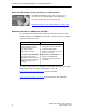
Preface, Contents Communication via Ethernet CPs in S7 Stations 1 SIMATIC NET NCM for Industrial Ethernet Installing and Starting the Ethernet CP with STEP 7 2 Manual SEND/RECEIVE interface 3 Configuring Communication Connections 4 Programming Functions (FCs) 5 NCM S7 Diagnostics 6 Firmware Loader 7 for NCM S7 V5.
Classification of Safety–Related Notices This manual contains notices which you should observe to ensure your own personal safety, as well as to protect the product and connected equipment. These notices are highlighted in the manual by a warning triangle and are marked as follows according to the level of danger: ! ! ! Danger indicates that death or severe personal injury will result if proper precautions are not taken.
Trademarks SIMATICR, SIMATIC HMIR and SIMATIC NETR are registered trademarks of SIEMENS AG. Third parties using for their own purposes any other names in this document which refer to trademarks might infringe upon the rights of the trademark owners. Safety Instructions Regarding your Product: Before you use the product described here, read the safety instructions below thoroughly. Qualified Personnel Only qualified personnel should be allowed to install and work on this equipment.
Prior to Startup Before putting the product into operation, note the following warning: Caution Prior to startup you must observe the instructions in the relevant documentation. For ordering data of the documentation please refer to the catalogs or contact your local SIEMENS representative. Copyright E Siemens AG 2001–2002 All rights reserved Disclaimer of Liability The reproduction, transmission or use of this document or its contents is not permitted without express written authority.
This Manual on SIMATIC NET NCM S7 for Industrial Ethernet ...supports you when using the communication services provided by the SIMATIC NET communications processors (Industrial Ethernet CPs) for communication on SIMATIC NET with Industrial Ethernet in the management and cell areas.
This Manual on SIMATIC NET NCM S7 for Industrial Ethernet Audience This manual is intended for personnel responsible for installing and programming STEP 7 programs and for service personnel. Scope of this Manual This manual applies to version 5.2 and higher of the NCM S7 configuration software for Industrial Ethernet and to version 5.2 and higher of the STEP 7 software. This version of the manual includes information relating to new functions in STEP 7 and NCM S7 as of V5.2.
This Manual on SIMATIC NET NCM S7 for Industrial Ethernet You will find additional information in the following sources: This manual is also part of the NCM S7 for Industrial Ethernet documentation package. These documents are also on the Manual Collection CD supplied with every S7-CP and they are also available on the Internet. The following table provides you with an overview.
This Manual on SIMATIC NET NCM S7 for Industrial Ethernet Quick Start CD: Samples covering all aspects of communication The Quick Start CD that can be ordered separately is a treasure-trove of sample programs and configurations. You can order this directly over the Internet at: http://www.ad.siemens.de/net/html_00/online_zugreifen.
This Manual on SIMATIC NET NCM S7 for Industrial Ethernet Access to Online Help of STEP 7 and NCM S7 With the online help, you can obtain the following information: S You can display the contents of the STEP 7 basic help system with the menu command Help –> Contents. S Context-sensitive help on the selected object using the Help –> Context-Sensitive Help menu command, the F1 function key or the question mark in the toolbar. F1 You can then access further information relating to the current topic.
Contents 1 Communication via Ethernet CPs in S7 Stations . . . . . . . . . . . . . . . . . . . . . . . . . . 13 1.1 Industrial Ethernet . . . . . . . . . . . . . . . . . . . . . . . . . . . . . . . . . . . . . . . . . . . . . . . 14 1.2 SIMATIC S7 Communication with S7 Ethernet CPs . . . . . . . . . . . . . . . . . . 15 1.3 1.3.1 1.3.2 PG/OP Communication via Industrial Ethernet . . . . . . . . . . . . . . . . . . . . . . PG Communication with STEP 7 over Industrial Ethernet . . . . . . . . . . .
Contents 5 6 4.2 Possible Connection Configurations . . . . . . . . . . . . . . . . . . . . . . . . . . . . . . . . 85 4.3 4.3.1 4.3.2 4.3.3 4.3.4 Connections . . . . . . . . . . . . . . . . . . . . . . . . . . . . . . . . . . . . . . . . . . . . . . . . . . . Creating a New Connection . . . . . . . . . . . . . . . . . . . . . . . . . . . . . . . . . . . . . . . Connections to Partners in Other Projects . . . . . . . . . . . . . . . . . . . . . . . . . . Further Functions . . . . . . . . . . . . . .
Contents 6.2.1 6.2.2 Installing and Starting NCM S7 Diagnostics . . . . . . . . . . . . . . . . . . . . . . . . . General Menu Commands . . . . . . . . . . . . . . . . . . . . . . . . . . . . . . . . . . . . . . . . 178 180 6.3 Starting Diagnostics – Establishing a Connection to the Ethernet CP . . . 182 6.4 How to Use Diagnostics . . . . . . . . . . . . . . . . . . . . . . . . . . . . . . . . . . . . . . . . . . 185 6.5 Call-Specific Diagnostic Functions . . . . . . . . . . . . . . . . . . . . .
Communication via Ethernet CPs in S7 Stations 1 The Ethernet CP for SIMATIC S7 provides a series of communications services for different tasks.
Communication via Ethernet CPs in S7 Stations 1.1 Industrial Ethernet Definition Within the open, heterogeneous SIMATIC NET communication system, Industrial Ethernet is the network for the management and cell level. Physically, Industrial Ethernet is an electrical network that uses a shielded coaxial cable or twisted pair or an optical network with fiber-optic cables. Industrial Ethernet is defined by the international standard IEEE 802.3 (see /11/).
Communication via Ethernet CPs in S7 Stations 1.
Communication via Ethernet CPs in S7 Stations S S7 communication S7 communication forms a simple and efficient interface between SIMATIC S7 stations and PGs/PCs using communication function blocks. S S5-compatible communication with SEND/RECEIVE interface Depending on the CP type, the SEND/RECEIVE interface allows program-controlled communication on a configured connection from a SIMATIC S7 PLC to another SIMATIC S7 PLC, to a SIMATIC S5 PLC, to PCs/PGs, and to any other station.
Communication via Ethernet CPs in S7 Stations S File management and file access with FTP The IT-CP (S7-400 / S7-300) provides additional functions for FTP services. You can use your S7 station both as an FTP client and as an FTP server (refer to the manual of the IT-CP /5/). – S7 Station as FTP Client You can transfer data blocks from or to a file server. – S7 Station as FTP Server Another station, for example, a PC transfers data blocks to or from the S7 station the file system on the IT-CP.
Communication via Ethernet CPs in S7 Stations Configuration and Diagnostics To connect and configure the Ethernet CP, you require the STEP 7 configuration software and the SIMATIC NET NCM S7 for Industrial Ethernet option. NCM S7 for Industrial Ethernet is installed as a STEP 7 option and is therefore integrated in STEP 7. NCM S7 for Industrial Ethernet also provides a wide range of diagnostic functions for the various types of communication.
Communication via Ethernet CPs in S7 Stations 1.3 PG/OP Communication via Industrial Ethernet Application PG/OP communication provides functions that are already integrated in every SIMATIC S7/M7/C7 device. A distinction must be made between the following two types of function: S PG communication PG communication with STEP 7 PLCs on Industrial Ethernet means the following: – You can use the complete range of functions of STEP 7 on Industrial Ethernet.
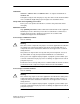
Communication via Ethernet CPs in S7 Stations Operator Interface functions PC with Ethernet CP OP Ethernet attachment STEP 7 NCM S7 Modem / ISDN Create configuration data for every CP and download to the Ethernet CPs Ethernet S7 – 400 S7 – 300 Ethernet CP WAN * * only TCP/IP S7 – 400 Ethernet CP Ethernet CP Figure 1-2 20 Configuration for PG/OP Operation SIMATIC NET NCM S7 for Industrial Ethernet C79000-G8976-C129–06
Communication via Ethernet CPs in S7 Stations 1.3.1 PG Communication with STEP 7 over Industrial Ethernet Requirements for PG Communication PG communication is possible when the following requirements are met: S An Ethernet CP is installed in the PG or engineering station or there is a modem/ISDN interface for remote access. S The Ethernet CP must have an address (default MAC address or set the IP address).
Communication via Ethernet CPs in S7 Stations 1.3.2 OP Operation: Connecting Operator Interface Devices via Industrial Ethernet Requirements Operation allowing operator interface functions is possible when the following conditions are met: S The operator interface device has: – an Ethernet CP installed – SOFTNET S7 for Ind. Ethernet or S7-1613/ WIN 95, WIN NT, MS-DOS, Windows installed. S The CPs in the S7 stations are supplied with a MAC/IP address (use the default MAC address or set an IP address).
Communication via Ethernet CPs in S7 Stations 1.4 S7 Communication on Industrial Ethernet Application S7 communication via Industrial Ethernet allows program-controlled communication using communication SFBs/FBs via configured S7 connections. Per job, up to 64 Kbytes of user data can be transmitted. The Ethernet CP acts as an “S7 communication relay” by passing on the S7 functions via Industrial Ethernet (see /8/).
Communication via Ethernet CPs in S7 Stations S Client and server functionality at one end only (S7 connections configured at one end) In the following situations, write and read functions can be implemented with PUT / GET: – S7 communication over router PG/PC stations can access S7 stations if the PG/PC stations are connected to a different subnet (PROFIBUS / Ethernet) via routers (for example, an IE/PB Link); in this case, S7 stations are servers. S7 communication is possible over a gateway.
Communication via Ethernet CPs in S7 Stations Configuring S7 Connections Create S7 connections to use S7 communication for data exchange between two SIMATIC S7 stations. For more detailed information, refer to the STEP 7 Description /6/ /8/. Notice S7 connections via routers are supported only within a STEP 7 project but not between partners in different STEP 7 projects of a multiproject! Interface in the User Program of the S7 Station You use SFBs (for S7-400) and FBs (for S7-300) in the user program.
Communication via Ethernet CPs in S7 Stations Notes on S7 communication between PC/PG station and S7 station Applications in a PC/PG station communicate with the S7 station over an OPC interface or SAPI-S7 interface for operator intervention, monitoring and control. The S7 stations use the integrated communication SFBs/FBs (client and server functionality at both ends).
Communication via Ethernet CPs in S7 Stations 1.5 S5-compatible Communication (SEND/RECEIVE Interface1) Application Using the SEND/RECEIVE interface, your S7 user program has access to S5-compatible communication with configured transport connections.
Communication via Ethernet CPs in S7 Stations IP (Internet Protocol) For internetwork data transmission, the following services are available with suitable CPs such as the CP 443-1 TCP: S ISO-on-TCP connection ISO-on-TCP is intended for reliable, internetwork data transmission. The ISO-on-TCP service corresponds to the TCP/IP standard (Transmission Control Protocol/Internet Protocol) with the RFC 1006 extension according to layer 4 of the ISO reference model (see /18/).
Communication via Ethernet CPs in S7 Stations Stations The SEND/RECEIVE interface allows program-controlled communication on Industrial Ethernet between the SIMATIC S7 PLC and the following: S SIMATIC S7 PLC with Ethernet CP S SIMATIC S5 PLC with Ethernet CP S PC/PG with Ethernet CP S Other station with Industrial Ethernet attachment S7 – 400 Ethernet CP S7 – 300 Ethernet CP D D D Ethernet D D D SIMATIC S5 with Ethernet CP D D D Other station with Ethernet attachment WAN Internet Router Fig
Communication via Ethernet CPs in S7 Stations 1.6 FETCH/WRITE Services (Server) Application In addition to the SEND/RECEIVE interface, the FETCH/WRITE functionality provides further services for S5-compatible communication on configured transport connections. The FETCH/WRITE interface is used primarily to attach SIMATIC S7 to SIMATIC S5 and to other non-S7 stations (for example PCs). S FETCH The partner on the connection (SIMATIC S5 or non-S7 station) can read system data on the SIMATIC S7 PLC.
Communication via Ethernet CPs in S7 Stations 1.7 Networking Stations with STEP 7 Configuring To allow stations to communicate with each other the networks must be configured in the STEP 7 projects. Configuring a network or subnet involves the following: 1. You create one or more subnets of the required subnet type in the project. 2. You select the properties of the subnet. Normally the default settings are adequate. 3. You connect the station “logically” to the subnet. 4.
Communication via Ethernet CPs in S7 Stations Variants Before configuring networks with STEP 7, you should be aware of the various configurations possible in the STEP 7 project.
Communication via Ethernet CPs in S7 Stations 1.7.1 Network/Project Variant: One Subnet – One Project Configuration of the System In the simplest case, your system consists of SIMATIC S7 stations connected by one subnet, for example of the type Industrial Ethernet. S7-400/1 S7-300/1 System “Production” Ethernet (1) S7-300/2 View in a STEP 7 Project You create an Industrial Ethernet object in the STEP 7 project.
Communication via Ethernet CPs in S7 Stations 1.7.2 Network/Project Variant: SIMATIC S5 and Non-SIMATIC Devices on the Subnet Configuration of the System In addition to SIMATIC S7 stations, SIMATIC S5 stations and non-SIMATIC devices can be included in your system. S7-400/1 System “Production” S7-300/1 Non-SIMATIC Ethernet (1) SIMATIC S5 S7-300/2 View in a STEP 7 Project SIMATIC S5 stations you intend to include in the communication can be selected directly.
Communication via Ethernet CPs in S7 Stations 1.7.3 Network/Project Variant: Two or More Subnets – One Project Configuration of the System Due to the different tasks of the stations or due to the extent of the system it may be necessary to operate more than one network.
Communication via Ethernet CPs in S7 Stations 1.7.4 Network/Project Variant: One Subnet – More Than One (Sub)Project Configuration of the System In complex networked systems, during configuration it is sometimes more efficient to manage plant sections in different (sub) projects. The situation can arise that communication takes place over an interproject subnet and that interproject connections must then also be created.
Communication via Ethernet CPs in S7 Stations to bring connections with identical connection names together. The topic of multiprojects is dealt with in detail in the STEP 7 basic help.
Communication via Ethernet CPs in S7 Stations Stations of the type SIMATIC S5 function in just the same way as representative objects. Merging projects in the multiproject: If you have used the multiproject functions allowing you to use connections to a partner in an unknown project, STEP 7 will automatically attempt to synchronize two separately configured connections.
Communication via Ethernet CPs in S7 Stations 1.7.5 Network/Project Variant: Several Subnets in Several (Sub) Projects Configuration of the System If several network types need to be used and if these need to be managed in different projects due to the different tasks of the stations or due to the large span of the plant, stations can be created as follows: S Using (sub) projects in the “multiproject” S by configuring ”Other stations / SIMATIC S5” in the other project.
Communication via Ethernet CPs in S7 Stations Representative Objects for Stations Outside the Current Project If you do not want to use the multiproject functions, you can fall back on the use of representative objects as used previously. To be able to network the representative objects, you must once again create a subnet of the type PROFIBUS in both projects as shown in the example here.
Communication via Ethernet CPs in S7 Stations 1.7.6 Network/Project Variant: Connections between Subnets (TCP/IP) Configuration of the System If connections are required to stations on network structures connected by routers due to the differing tasks of the stations or the large span of the network, the stations in the other project can be reached by configuring “Other Stations”.
Communication via Ethernet CPs in S7 Stations - 42 SIMATIC NET NCM S7 for Industrial Ethernet C79000-G8976-C129–06
Installing and Starting the Ethernet CP with STEP 7 2 To attach a SIMATIC station to Industrial Ethernet via the Ethernet CP, configure the CP with the NCM S7 configuration software.
Installing and Starting the Ethernet CP with STEP 7 2.1 General Information About the NCM S7 for Industrial Ethernet Option Installation Please follow the instructions in the README file when installing the NCM S7 for Industrial Ethernet option on your PG/PC under STEP 7. Functions NCM S7 consists of the following: S CP-specific index dialogs that you call using the properties dialog box of the modules.
Installing and Starting the Ethernet CP with STEP 7 2.2 Procedure A CP is managed in an S7 project just as the other modules. You use STEP 7 to configure the hardware and create and manage the user software (see /6/). Configuring a CP involves the following basic steps (the broken lines indicate options): Create the Industrial Ethernet subnet (see 2.2.1) Check or set the network properties Enter the Ethernet CP in the hardware configuration (see 2.2.
Installing and Starting the Ethernet CP with STEP 7 2.2.1 Creating an Industrial Ethernet Subnet Aims To be able to attach the SIMATIC stations to a subnet, you create the subnet in your project. This means that all the parameters for the entire subnet are managed centrally. Procedure It is advisable to create the subnet before you configure the stations since the assignment of the SIMATIC stations is then performed largely automatically.
Installing and Starting the Ethernet CP with STEP 7 3. If you prefer a NetPro graphic network display, select the network object “Ethernet” and confirm with Edit " Open Object. Figure 2-2 Graphic Network Representation (here showing stations not yet networked) From this graphic representation, you can also activate all the functions for networking and configuring connections with the Ethernet CPs.
Installing and Starting the Ethernet CP with STEP 7 Notice Preserving Consistency in Merged Subnets After merging the subnets, you should check the consistency throughout the multiproject using the menu command Network > Check Interproject Consistency in NetPro to make sure that there is consistency throughout the multiproject. This check detects, for example, S7 subnet IDs that are not unique within the multiproject.
Installing and Starting the Ethernet CP with STEP 7 2.2.2 Entering an Ethernet CP in the Hardware Configuration Procedure By installing and assigning the Ethernet CP in the rack of a SIMATIC station, you establish the logical attachment between the Internet CP and the subnet. 1. Select the station in your project that you want to attach to Industrial Ethernet using an Ethernet CP. 2.
Installing and Starting the Ethernet CP with STEP 7 Note You can open the dialog for setting the interface at any time from the Properties dialog of the CP in the “General” tab. 1. If you have not yet created a subnet in the project or have not yet created the selected subnet, you can now create a subnet. To do this, select the “New” button. Result: An object of the type network is created in the project. 2. Check the addresses and if necessary change them.
Installing and Starting the Ethernet CP with STEP 7 Setting Addresses in the Configuration and Addressing for the First Time The address settings described here are made on the CP only after you download the configuration data. With the latest Ethernet CPs, the situation is as follows: To be able to reach the CP using these addresses before you download the configuration data, you can address the CP using its default MAC address and then supply it with project-specific address information.
Installing and Starting the Ethernet CP with STEP 7 2.2.3 Displaying the Network Attachments of a Station Procedure You can easily get an overview of the network attachment configurations of a SIMATIC station in one of the following ways: S A graphic overview in NetPro; S An overview in table form in the Properties dialog of the station Graphic Overview in NetPro The NetPro view provides you with a good overview of the networked stations: Follow the steps below: 1.
Installing and Starting the Ethernet CP with STEP 7 Overview in Table Form The table view in the Properties dialog of the station provides a detailed overview of the components used for network attachment. Follow the steps below: 1. Using the SIMATIC Manager, select the station in your project that you want to check. 2. Select the Object Properties using the menu option Edit or by double-clicking the station symbol. " Object Properties 3. Select the “Interfaces” tab.
Installing and Starting the Ethernet CP with STEP 7 2.2.4 Setting Further CP Properties Overview In addition to the network attachment, you can also make further settings for the specific module or you can call functions. 1. Select the Ethernet CP in the hardware configuration. 2. Select Edit " Object Properties. In the dialog, you will see further tabs in addition to the “General” tab described in Section 2.2.
Installing and Starting the Ethernet CP with STEP 7 Notice Please note the following information on S7–300 stations: If you selected the option ”Update OB1 process image cyclically” in the CPU configuration, (default), make sure that the start address of the CP is outside the process image area (start addresses in the ”Addresses” tab). Example: if the process image selected for the CPU = 1024 (0...1023), an address >= 1024 must be selected for the CP.
Installing and Starting the Ethernet CP with STEP 7 Table 2-1 Settings in the “Options” Tab , continued Option S Replace Module without PG Meaning / Effect With this option, you can have the configuration data of the CP stored on the CPU. If you then replace CP, the configuration data for the new CP are downloaded automatically from the CPU when the CP is started up. If you select this option, the configuration data are stored long-term on the CPU instead of in the EEPROM of the CP.
Installing and Starting the Ethernet CP with STEP 7 Table 2-1 Settings in the “Options” Tab , continued Option S Individual Network Settings Meaning / Effect Here, you can make fixed network settings, when necessary. As default, “Automatic Setting” is selected and this setting generally guarantees problem-free communication in most situations.
Installing and Starting the Ethernet CP with STEP 7 Table 2-1 Settings in the “Options” Tab , continued Option S Multiplex OP Connections / Reserve Internal CPU Connection Resources Meaning / Effect To attach TD/OPs or HMI devices, you can optimize the connection resources on the S7-300 CPU by having up to 16 of these devices communication on a single CPU connection resource (multiplex mode).
Installing and Starting the Ethernet CP with STEP 7 Diagnostics Tab In the “Diagnostics” tab, you can start NCM S7 Ethernet Diagnostics. See Chapter 6 Diagnostics for a description of the diagnostic functions themselves. Addressing Tab In the ”Addressing” tab, you can assign the previously configured IP address and IP parameters to the CP. This is necessary before the configuration data can be downloaded to the CP over Ethernet. For a detailed description, refer to Section 2.3.
Installing and Starting the Ethernet CP with STEP 7 2.2.5 “Substitute Objects” in the STEP 7 Project Overview Communication connections can be configured fully when the communications partners are available in the current project.
Installing and Starting the Ethernet CP with STEP 7 Procedure To enter a substitute object in the project, following the steps below: 1. Select the project in the SIMATIC Manager. 2. Select the menu command Insert " Station " and then as necessary Other Station, PG/PC or SIMATIC S5. Possible result: the selected object is created in the project.
Installing and Starting the Ethernet CP with STEP 7 Figure 2-7 Selecting the Subnet Type for “Other Station” (Example) 3. Select a subnet. Result: The “Properties – Ethernet Interface” dialog is displayed. Here, you can select the subnet, connect the station to the network and set the address (MAC, IP). All the SIMATIC stations in the project can establish communication relationships to this substitute object.
Installing and Starting the Ethernet CP with STEP 7 2.2.6 Configuring Communication Services Setting Up Connections You must set up connections for the connection-oriented services supported by the Industrial Ethernet CP, see also the Table in Section 1.2. S S7 connections see the STEP 7 user manual /6/ S ISO transport connections see Section 4.4 S ISO-on-TCP connections see Chapter 4.5. S TCP connections see Section 4.6 S Connections for UDP see Section 4.7.
Installing and Starting the Ethernet CP with STEP 7 2.3 Assigning Addresses for the First Time (Applies to Latest CPs) Meaning of the Address Assignment – MAC Address and IP Address The CP ships with a factory-set MAC address. Without further configuration, the device can only be accessed over the Ethernet port using this MAC address.
Installing and Starting the Ethernet CP with STEP 7 Requirements Before you can use the addressing described here, the CP must be obtainable online, which means: S An attachment to the Ethernet LAN must already exist; there must be no routers between subnets in the path. S The Ethernet port of your PG/PC must be accessible to STEP 7.
Installing and Starting the Ethernet CP with STEP 7 3. Start a network search for available modules by selecting the “Browse...” button. 4. Select the CP with the matching MAC address from the components listed. 5. Enter the required IP parameters and assign them to the CP. Result: The CP is now accessible on Industrial Ethernet using the IP address. Note You will find further detailed information on this procedure in the STEP 7 online help.
Installing and Starting the Ethernet CP with STEP 7 Alternative Procedure You can also follow the steps outlined below in the SIMATIC Manager: 1. Use the menu command PLC" Display Accessible Nodes to display the nodes that you can access over Industrial Ethernet. 2. Select the required node in the list displayed. 3. Then select the menu command PLC" Ethernet Address. Result: The previously selected node is entered directly into the ”Addressing” dialog. You cannot modify the MAC address of the node. 4.
Installing and Starting the Ethernet CP with STEP 7 2.3.2 Addressing using the Properties Dialog in HW Config or NetPro Follow the steps below to assign the IP address the first time: 1. Open the SIMATIC Manager. 2. Define the configuration of your S7 station with the appropriate components in HW Config in an existing or newly created project. 3. When you create the CP, network it with an Industrial Ethernet subnet.
Installing and Starting the Ethernet CP with STEP 7 2.4 Downloading the Configuration Data to the Target System Principle The configuration data of the Ethernet CP are downloaded from the hardware configuration. All the configuration data of the S7 station are downloaded including the central configuration, all relevant DP master systems and all parameter settings. The data of the configured connections must also be downloaded, see below.
Installing and Starting the Ethernet CP with STEP 7 Procedure To download the configuration data to the S7 station, follow the steps outlined below: 1. Open the “Set PG/PC Interface” dialog box in the Windows Control Panel. 2. Set the PG/PC interface according to the CPs available on your PG and according to the bus attachment (interface parameter assignment used). For more detailed information, refer to the integrated help system. F1 3.
Installing and Starting the Ethernet CP with STEP 7 Relocating the CP in the Hardware Configuration If you are using communication services with configured connections, the connection IDs also identify the slot of the CP. If you “drag” a CP you have already configured to a different slot, note the following: Notice If you drag the CP to a different slot, the data of the connection configuration are automatically updated.
Installing and Starting the Ethernet CP with STEP 7 72 SIMATIC NET NCM S7 for Industrial Ethernet C79000-G8976-C129–06
SEND/RECEIVE Interface in the User Program 3 This chapter explains the following: S How to send and receive data. S Which data areas can be used on the S7 CPU. S How to program the SEND/RECEIVE interface in the user program. You will find further information in the following sources: S For programming and configuring nodes for connections (for example a SIMATIC S5 PLC with the CP 1430 TCP, PC with CP 1413), please refer to the appropriate manuals.
SEND/RECEIVE Interface in the User Program 3.1 How the SEND/RECEIVE Interface Works on the CPU Functions (FCs) The following functions (FCs) are available for handling communication on connections: S AG_SEND/AG_LSEND This block takes the user data from the specified user data area and transfers it to the Ethernet CP. S AG_RECV/AG_LRECV This block transfers received user data to the user data area specified in the call. The diagram below illustrates the situation.
SEND/RECEIVE Interface in the User Program 3.2 Programming the SEND/RECEIVE Interface Principle of Job and Data Transfer The user program triggers the transfer of the user data areas with FC calls and monitors the transfer by evaluating the return codes of the FCs. The following parameters are transferred when the FCs are called: S The number of the connection (ID) S The location of the user data area in the CPU For detailed information about the call interface see Chapter 5.
SEND/RECEIVE Interface in the User Program Calling FCs in the CPU Program One possible sequence for FCs in conjunction with the organization and program blocks in the CPU cycle is illustrated in the following diagram.
SEND/RECEIVE Interface in the User Program S At various points (event and program-controlled) the user program sends data on a connection using the AG_SEND call. S At various points in the CPU cycle, the user program accepts the data received on the connection using an AG_RECV call. Note The blocks can also be called more than once in a cycle for the same communication connection.
SEND/RECEIVE Interface in the User Program 3.3 Data Exchange S7 CPU <–> Ethernet CP The Ethernet CP processes the send and receive jobs independent of the CPU cycle and requires one transmission time. The interface to the user program with the FCs is synchronized by an acknowledgment. Two situations must be distinguished: S The CPU cycle is faster than the transmission time. S The CPU cycle is slower than the transmission time. Note Please refer to the sequence charts for the FCs in Chapter 5.
SEND/RECEIVE Interface in the User Program Notice Remember that resource shortages can occur if the processing speeds on the sender and receiver are not the same (sender faster than receiver). The sender receives a message from the FCs if problems occur (“No resources on the destination station”).
SEND/RECEIVE Interface in the User Program 3.4 3.4.1 Additional Information Programming Data Transfer on TCP Connections Purpose of TCP Connections TCP connections should be used above all for connections to systems of a different type if they do not support RFC1006. For communication between devices of the SIMATIC family, you should use the more convenient ISO-on-TCP connections! The following sections explain certain special points to note.
SEND/RECEIVE Interface in the User Program 3.4.2 Recommendations for Use with a High Communications Load Overview The points below will help you to avoid overload situations on your CPU when using the Ethernet CPs. In particular when you replace an older CP with a newer CP and are then confronted with overload problems, you should check your application for the pitfalls outlined below. Known Problems S The functions for sending and receiving (FC5/FC6 or FC50/60) are often called cyclically in OB1.
SEND/RECEIVE Interface in the User Program - 82 SIMATIC NET NCM S7 for Industrial Ethernet C79000-G8976-C129–06
Configuring Communication Connections 4 This chapter explains the following: S The general aspects of configuring communication connections S How to configure ISO transport connections, ISO-on-TCP and TCP connections S How to use the connection configuration functions to specify communication partners that exchange data via UDP You will find a description of the connection-specific properties dialogs in the following sections: S ISO transport connections see Section 4.
Configuring Communication Connections 4.1 Procedure Steps The following steps are necessary to operate connections on the SIMATIC S7 PLC with the Ethernet CP: Configuring Programming If necessary, configure “Other Station” for connections using the appropriate tool. Create new connections Program the SEND/RECEIVE interface in the user program. (Refer to Section 3.2 and the detailed FC description in Chapter 5). Configure connection properties.
Configuring Communication Connections 4.2 Possible Connection Configurations Communication connections are possible between the communication partners shown in the diagram below. The communication partners can be in the same project or distributed in the subprojects of a multiproject. Connections to communication partners outside a project are configured using the STEP 7 object “Partner other project” or using substitute objects such as ”Other stations” or SIMATIC S5.
Configuring Communication Connections Organization in a Multiproject If interproject subnets are configured, you can also configure connections over such subnets using STEP 7 V5.2. The endpoints of these connections can be located in different projects. STEP 7 supports you both when creating interproject connections within a multiproject as well as when synchronizing connections that were configured without a multiproject context.
Configuring Communication Connections 4.3 Connections Characteristics of a Connection A communication connection allows program-controlled communication between two nodes on Industrial Ethernet with the following characteristics: S The data transfer is bi-directional, in other words, it is possible to transmit and receive on the connection simultaneously. S Both stations have the same rights, in other words, each station can trigger the send and receive procedures in response to events.
Configuring Communication Connections Amounts of Data Refer to the manual /1/ supplied with the Ethernet CP for the number of communication connections supported by the Ethernet CP. The number of connections per station can be increased by adding more CPs.
Configuring Communication Connections Requirements for Configuring Connections The Ethernet CP was entered in the hardware configuration and connected to the subnet. As a bus node, the Ethernet CP has an address. Notice All stations not in the STEP 7 project must be configured with substitute objects (for example as “SIMATIC S5” or “Other stations”). or Use the “unspecified” partner type when you create the connection.
Configuring Communication Connections 4.3.1 Creating a New Connection Principle When you create new connections, you start from entered and networked stations. A connection is then configured starting from a station or CPU in the current S7 project and then selecting a destination station. Due to the networking, the node addresses (MAC or IP addresses) of the two stations are already decided.
Configuring Communication Connections SIMATIC NET NCM S7 for Industrial Ethernet C79000-G8976-C129–06 91
Configuring Communication Connections Figure 4-4 Layout of the “New Connection” Dialog (Example of an ISO Transport Connection) 3. Select the partner station to which you want to establish a connection (if several CPUs exist, please select the required CPU). 4. Select the connection type you want to use (for example ISO transport connection) in the “Type” box When you confirm your input with Apply, the new connection is created and the ”New Connection” dialog box remains open.
Configuring Communication Connections Handling Connections in a Multiproject Interproject connections to a specified partner (for example, a CPU) are created in the same way as connections within a project (identical procedure). The dialog for selecting the connection partner has been extended and allows you not only to select the endpoint (module) but also the project within a multiproject to which the endpoint belongs.
Configuring Communication Connections In both projects, the same connection name must be configured in the properties of the connection. The connection name is used as a textual reference when the projects are merged. Based on the connection name it is possible to assign the connection partner and synchronize the connection properties. Before the projects are merged, such connections are ”unspecified connections” in terms of addressing; in other words, the partner addresses remain empty.
Configuring Communication Connections The free UDP connection is another variant. With this type of connection, the address of the connection partner is left open during configuration. The communication nodes are identified by address information in the communication job in the user program. For further information, refer to the sections dealing with specific connections. Notice The number of connections possible per Ethernet CP can be found in the manual /1/supplied with the CP.
Configuring Communication Connections 4.3.3 Further Functions Toolbar In the toolbar of the connection configuration dialog the following functions are available: Save To save the configured connection, select the Save function or click the save button. Print You can print the entire connection table or individual sections of it by selecting the Print function or clicking the print button.
Configuring Communication Connections 4.3.4 Connections Without Assignment Overview This section explains the actions that can lead to a configured connection losing its assignment to the CP or being deleted. Caution Remember that in contrast to the S7 connections, the connections of the SEND/RECEIVE interface are assigned a CP-dependent ID. The actions below may require the ID to be modified so that the interface information in the user program must also be adapted.
Configuring Communication Connections Table 4-3 Actions That Can Cause Changes to Configured Connections, continued Action Consequences for the Connections How to Establish the Connection Again Deleting a remote station. The connections of the stations in the project to remote stations remain without assignment in the connection table. In the “Overview” tab of the Properties dialog, the connections are identified with “!”.
Configuring Communication Connections 4.4 Configuring ISO Transport Connections Introduction As well as the entry in the connection table, you can also modify special properties for each configured connection. Here, you can change specific connection parameters that were entered as defaults during the new connection dialog. Opening the Dialog To call the dialog for special connection properties, follow the steps outlined below: 1. Select the required connection in the connection table. 2.
Configuring Communication Connections 4.4.1 Specifying the Local Connection Endpoint General Tab This tab of the Properties dialog displays general connection parameters that identify the local connection endpoint.
Configuring Communication Connections Attributes Description Access ID The entry is identical to the Local ID parameter in the connection list. Selectable Name When you create the connection, a name is proposed here along with a connection number as suffix. Modifiable Local Endpoint With unspecified connections, use this box to identify the partner. Via CP If the station contains more than one CP of the same type connected to the same subnet, you can select the connection route.
Configuring Communication Connections 4.4.2 Specifying ISO Transport Addresses Address Parameters An ISO transport connection is specified by the local and remote connection endpoint.
Configuring Communication Connections Addresses Tab The addresses tab displays proposed values for the relevant local and remote address information. When connecting to non-S7 stations, you can set the TSAP addresses individually. Figure 4-8 Layout of the “Addresses” Tab of the Properties Dialog with Default TSAPs TSAP Format ISO transport connections have a TSAP length of 1 to 16 bytes. When you are entering values, the current length is displayed automatically (visible display: 20 ASCII characters).
Configuring Communication Connections Default TSAPs When configuring the local and remote TSAPs, there is a default value “ISO-1” for the first connection between the two partners (can be changed). For a new connection between the two partners, the default value “ISO-2” is proposed. With a new connection to a new partner, the value ISO-1 is used again.
Configuring Communication Connections 4.4.3 Specifying ISO Transport Dynamic Properties Dynamics Tab The Dynamics tab displays the relevant timers and counters of this connection. You can normally accept these default values. If necessary, for example with connections to non-Simatic systems, you can set the timers and counters individually and influence the dynamic response of the connection.
Configuring Communication Connections Attributes Description Access Inactivity Time The inactivity time specifies the interval after which the connection is terminated if no sign of life is received from the partner (6–180 s, default 30 s). Modifiable Window Time The window time specifies the interval at which sign Display only of life frames are sent. For SIMATIC NET CPs, the window time is set to 1/3 of the inactivity time (2–60 s, default 10 s).
Configuring Communication Connections 4.4.4 ISO Transport with the FETCH/WRITE Mode Using FETCH PASSIVE / WRITE PASSIVE If you select one of the FETCH PASSIVE or WRITE PASSIVE modes for the ISO transport connection, you can access the system areas on a SIMATIC S7 PLC from a SIMATIC S5 station or other non-S7 station. Figure 4-11 The connection can then only be used for this mode; sending or receiving with the FCs AG_SEND/AG_LSEND or AG_RECV/AG_LRECV is then no longer possible.
Configuring Communication Connections Notice Remember that with this configuration on an S7-300, one connection resource (free connection for S7 functions) of the S7-300 CPU is used. CPU connection resources are also used, for example, by S7-300 CPs, in the FMS mode or by PGs and OPs. For more detailed information about the maximum connection resources, refer to /13/ and /7/.
Configuring Communication Connections 4.4.5 Checking ISO Transport Connection Properties Overview Tab The Overview tab displays all previously configured ISO transport connections and their parameters for this station (information only). For an example of this display, refer to Section 4.3.4. Description Parameter Local ID This is the connection ID of the ISO transport connection Name Entered connection name. This identifies the ISO transport connection.
Configuring Communication Connections 4.5 Configuring ISO-on-TCP Connections Properties Introduction As well as the entry the connection table, you can also modify specific connection parameters that were entered as defaults during the New connection dialog. Opening the Dialog To call the dialog for special connection properties, follow the steps outlined below: 1. Select the required connection in the connection table. 2.
Configuring Communication Connections 4.5.1 Specifying the Local Connection Endpoint General Tab This tab of the Properties dialog displays general connection parameters that identify the local connection endpoint.
Configuring Communication Connections Parameter Description Access ID The entry is identical to the Local ID parameter in the connection list. Selectable Name When you create the connection, a name is proposed here along with a connection number as suffix. Modifiable Local Endpoint With unspecified connections, use this box to identify the partner. Via CP If the station contains more than one CP of the same type connected to the same subnet, you can select the connection route.
Configuring Communication Connections 4.5.2 Specifying ISO-on-TCP Addresses Address parameter A connection is specified by the local and remote connection endpoint.
Configuring Communication Connections Addresses Tab The addresses tab displays proposed values for the relevant local and remote address information. If necessary, you can set the TSAP addresses individually. Figure 4-14 Layout of the “Addresses” Tab of the Properties Dialog with Default TSAPs for ISO-on-TCP Connections TSAP Format ISO-on-TCP connections have a TSAP length of 1 to 16 bytes.
Configuring Communication Connections Default TSAPs When configuring the local and remote TSAPs, there is a default value “TCP-1” for the first connection between the two partners (can be changed). For a new connection between the two partners, the default value “TCP-2” is proposed. With a new connection to a new partner, the value TCP-1 is used again.
Configuring Communication Connections 4.5.3 ISO-on-TCP with the FETCH/WRITE Mode Using FETCH PASSIVE / WRITE PASSIVE If you select one of the FETCH PASSIVE or WRITE PASSIVE modes for the ISO-on-TCP connection, you can access the system areas on a SIMATIC S7 PLC from a SIMATIC S5 station or other non-S7 station. Figure 4-16 The connection can then only be used for this mode; sending or receiving with the FCs AG_SEND/AG_LSEND or AG_RECV/AG_LRECV is then no longer possible.
Configuring Communication Connections Notice Remember that with this configuration on an S7-300, one connection resource (free connection for S7 functions) of the S7-300 CPU is used. CPU connection resources are also used, for example, by S7-300 CPs, in the FMS mode or by PGs and OPs. For more detailed information about the maximum connection resources, refer to /13/ and /7/.
Configuring Communication Connections 4.5.4 Checking ISO-on-TCP Connection Properties Overview Tab The overview shows all the configured ISO-on-TCP connections and their parameters (cannot be modified here). You can adjust the width of the columns in the table. For an example of this display, refer to Section 4.3.4 (the ISO transport connection). Parameter Description Local ID This is the connection ID of the ISO-on-TCP connection (STEP 7 connection configuration; DWORD) Name (loc.
Configuring Communication Connections 4.6 Configuring TCP Connection Properties Introduction After the entry in the connection table, you can modify specific connection parameters for each configured connection that were given default values when you created the connection. Opening the Dialog To call the dialog for special connection properties, follow the steps outlined below: 1. Select the required connection in the connection table. 2.
Configuring Communication Connections 4.6.1 Specifying the Local Connection Endpoint General Tab This tab of the Properties dialog displays general connection parameters that identify the local connection endpoint.
Configuring Communication Connections Attributes Description Access ID The entry is identical to the Local ID parameter in the connection list. Selectable Name (loc. endpoint) When you create the connection, a name is proposed here along with a connection number as suffix. Modifiable Local Endpoint With unspecified connections, use this box to identify the partner.
Configuring Communication Connections 4.6.
Configuring Communication Connections Addresses Tab – Specified TCP Connection The addresses tab displays proposed values for the relevant local and remote address information. You can change the port settings individually. Figure 4-19 Layout of the Properties Dialog in the “Addresses” tab with DEFAULT Ports for TCP Connections Ports The ports or port addresses define the access point to the user program within the station / CPU.
Configuring Communication Connections Addresses Tab – Unspecified TCP Connection If you select the partner type as “unspecified”, depending on your task, you can enter address information about the communication partner here. The options available to you are explained in detail in Section 4.3.1. The Addresses tab shown here illustrates the situation in which the remote port but not the IP address was specified.
Configuring Communication Connections 4.6.3 TCP with the FETCH/WRITE Mode Using FETCH PASSIVE / WRITE PASSIVE If you select one of the FETCH PASSIVE or WRITE PASSIVE modes for the TCP connection, you can access the system areas on a SIMATIC S7 PLC from a SIMATIC S5 station or other non-S7 station. Figure 4-21 The connection can then only be used for this mode; sending or receiving with the FCs AG_SEND/AG_LSEND or AG_RECV/AG_LRECV is then no longer possible.
Configuring Communication Connections Notice Remember that with this configuration on an S7-300, one connection resource (free connection for S7 functions) of the S7-300 CPU is used. CPU connection resources are also used, for example, by S7-300 CPs, in the FMS mode or by PGs and OPs. For more detailed information about the maximum connection resources, refer to /13/ and /7/.
Configuring Communication Connections 4.6.4 Checking TCP Connection Properties Overview Tab The overview shows all the previously configured TCP connections and their parameters (cannot be modified here). For an example of this display, refer to Section 4.3.4 (the ISO transport connection). Parameter Description ID This is the connection ID of the TCP connection (STEP 7 connection configuration; DWORD). Name (loc. endpoint) Entered connection name.
Configuring Communication Connections 4.7 Configuring UDP Connection Properties Introduction After the entry in the connection table, you can modify specific connection parameters for each configured connection that were given default values when you created the connection. Opening the Dialog To call the dialog for special connection properties, follow the steps outlined below: 1. Select the required connection in the connection table. 2.
Configuring Communication Connections 4.7.1 Specifying the Local Connection Endpoint General Tab This tab of the Properties dialog displays the parameters of the connection and a local connection name for the UDP connection. The local ID is identical to the ID in the NetPro connection table (STEP 7 connection configuration) and is shown here to illustrate the assignment.
Configuring Communication Connections Attributes Description Access ID The entry is identical to the Local ID parameter in the connection list. Selectable Name When you create the connection, a name is proposed here along with a connection number as suffix. Modifiable Local Endpoint With unspecified connections, use this box to identify the partner.
Configuring Communication Connections 4.7.2 Specifying UDP Addresses Address Parameters and Connection Types With UDP, the communication partners are addressed using the local and remote endpoint, as follows. S Local addresses: Local IP address and local port S Remote addresses: Remote IP address and remote port Note The term “connection” is also used here for UDP. Reason: During configuration (just as in TCP) the communication partners are assigned to each other and therefore logically “connected”.
Configuring Communication Connections Addresses Tab – Specified UDP Connections The addresses tab displays proposed values for the relevant local and remote address information. You can make the settings for the ports individually. Figure 4-24 Layout of the Properties Dialog in the “Addresses” tab with DEFAULT Ports for UDP Connections Ports The ports or port addresses define the access point to the user program within the station / CPU.
Configuring Communication Connections Addresses Tab – Unspecified UDP Connection An unspecified UDP connection can be used in two ways: S Free UDP Connection To configure a free UDP connection, select the “Address assignment in block” check box. The input boxes for the remote IP address and the remote port are then deactivated since the destination addresses are now specified by the user program.
Configuring Communication Connections 4.7.3 UDP with Broadcast and Multicast Application When you select the connection partner, you have the following two extra options on UDP connections: S Connection to all Broadcast Nodes If you select the “all broadcast nodes”, you specify that UDP frames are sent to all obtainable broadcast nodes.
Configuring Communication Connections Why Does an S7-CP Prevent Reception on Broadcast Connections? It is often necessary for one station to send frames to a number of partner stations. It is important that the frames are sent at the same time and arrive and practically the same time. Sending and receiving broadcast frames is always required. A broadcast message is received by all nodes in the network.
Configuring Communication Connections Addresses Tab – Connection to all Broadcast Nodes If you select “all broadcast nodes” as the connection partner, you specify that UDP frames are sent to all obtainable broadcast nodes. In the “Addresses” tab, a valid broadcast address in the network is proposed for the partner under the IP address (IP). You must enter a PORT address suitable for all partners you want to reach under PORT.
Configuring Communication Connections Addresses Tab – Connection to all Multicast Nodes By selecting “all multicast nodes” as the connection partner, you specify that S sent UDP frames are delivered to all multicast nodes of the multicast group; S the local device receives multicast frames in the specified multicast group. In the “Addresses” tab, a valid multicast address in the network is proposed for the partner under the IP address (IP).
Configuring Communication Connections 4.7.4 Checking the Properties of a UDP Connection Overview Tab At the overview level, all the configured UDP connections and their parameters in this station are displayed (cannot be modified). For an example of this display, refer to Section 4.3.4 (the ISO transport connection). Parameter Description Local ID This is the connection ID of the UDP connection (STEP 7 connection configuration; DWORD). Name (loc. endpoint) Entered connection name.
Configuring Communication Connections 4.7.5 Free UDP Connection Program-Controlled Addressing A free UDP connection allows program-controlled addressing of the communication partner. Communication between two nodes on Industrial Ethernet has the following properties: S Data transfer is bi-directional; in other words it is possible to send and receive on the UDP connection at the same time. S The local node is specified in the configuration.
Configuring Communication Connections 4.8 Routing to Distribute Load Routing to Distribute Load If more than one CP of the same type exists in a station and is connected to the same subnet, the route can be selected. Click the “Route” button in the “General” tab to display the route dialog: If you have configured a load distribution on two or more Ethernet CPs at the local or remote end, you can assign the connection to the required route via the CP.
Programming FCs (Functions) and FBs for S7 Ethernet CPs 5 Ready-made blocks form the interface to some of the communications services available with the Ethernet CPs. This chapter includes a detailed description of these blocks.
Programming FCs (Functions) and FBs for S7 Ethernet CPs 5.1 General Notes on FCs / FBs Block Library The functions (FCs) and function blocks (FBs) described here are supplied with the STEP 7 basic package unless indicated otherwise. The following list shows the numbers of the FCs as they are supplied with the configuration tool. You can change these numbers.
Programming FCs (Functions) and FBs for S7 Ethernet CPs Which Block Version Should I Use? The following descriptions also include information on differences between the various block versions. Please take note of the version identifiers of the blocks you are using. The SIMATIC Manager block libraries installed with STEP 7 / NCM S7 contain the block versions that were current at the time of the STEP 7 release. Note We recommend that you always use the latest block versions for all module types.
Programming FCs (Functions) and FBs for S7 Ethernet CPs Notice Please remember that if you replace a module, you must only use the blocks permitted for the configured CP type in the user program. This means: S If you replace the module without adapting the configuration data to the possibly newer module type, you do not need to make any changes to the blocks used.
Programming FCs (Functions) and FBs for S7 Ethernet CPs 5.2 Setting Parameters for FC Calls Before describing the FCs in detail, a few general comments on calling and setting parameters for FCs will be useful in this point.
Programming FCs (Functions) and FBs for S7 Ethernet CPs Setting Block Parameters Automatically1) To ensure correct parameter settings for the block calls, The LAD/STL/FBD editor in STEP 7 provides you with the option of accepting all the relevant parameters from the hardware configuration (HW Config) and from the connection configuration. When assigning the parameters for the block in the user program, follow the steps outlined below: 1. Select the block call and its block parameters; 2.
Programming FCs (Functions) and FBs for S7 Ethernet CPs 5.2.2 Parameters for Specifying a CPU Data Area (input parameters) Specifying the Data Area on the CPU When you call an FC, you transfer the address and length of the data area on the CPU in which the user data are available or will be stored or which can contain further parameter information. The ANY pointer data type is used to address this area.
Programming FCs (Functions) and FBs for S7 Ethernet CPs 5.
Programming FCs (Functions) and FBs for S7 Ethernet CPs CPU Ethernet CP Ethernet CP CPU STEP 7 user program STEP 7 user program User data areas User data areas AG_SEND send receive AG_RECV send AG_SEND Connection AG_RECV receive Note Unless specifically stated otherwise, the information on this and the following pages refers to AG_SEND / AG_LSEND or AG_RECV / AG_LRECV. Specifying the Data Area on the CPU When you call an FC, you transfer the address and length of the data area in the CPU.
Programming FCs (Functions) and FBs for S7 Ethernet CPs Table 5-1 FC ISO Transport ISO-on-TCP TCP UDP AG_LSEND (S7-400) 8192 bytes 8192 bytes 8192 bytes 2048 bytes 8192 bytes 8192 bytes 8192 bytes 2048 bytes AG_SEND (S7-300) AG_LRECV (S7-400) AG_RECV (S7-300) Note For information on the length of the data area you can transfer with older versions of the Ethernet CPs, refer to the product information bulletin / manual of the Ethernet CP you are using /1/.
Programming FCs (Functions) and FBs for S7 Ethernet CPs Working with the Job Header Free UDP connections require a job header in the user data area. The following schematic illustrates the structure of the job buffer and the meaning and location of the parameters in the job header.
Programming FCs (Functions) and FBs for S7 Ethernet CPs 5.3.1 FC5 AG_SEND / FC50 AG_LSEND Meaning of the Block The FCs AG_SEND / AG_LSEND pass data to the Ethernet CP for transfer over a configured connection. The selected data area can be a process image area, a memory bit area or a data block area. Error-free execution of the function is indicated when the entire user data area could be sent on Ethernet.
Programming FCs (Functions) and FBs for S7 Ethernet CPs Notice Please not the following special feature on TCP connections: With the S7-CPs for S7-400, you must use FC AG_LSEND on TCP connections! With the latest S7-CPs for S7-300, you must also use FC AG_SEND for TCP connections. How the Block Works The following diagram illustrates the normal sequence of data transmission triggered in the user program using AG_SEND. The send job in executed as soon as the parameter ACT = 1 is passed.
Programming FCs (Functions) and FBs for S7 Ethernet CPs User program (CPU cycle) Ethernet CP Communications Partner Supply AG_SEND with data “X” ACT = 1 AG_SEND 0, 0, 81811) Transfer “X” active on Ethernet Supply AG_SEND ACT = 0 AG_SEND 0, 0, 81811) AG_SEND 1, 0, 00001) Time Time Time Legend: 1) parameter transfer DONE, ERROR, STATUS 154 SIMATIC NET NCM S7 for Industrial Ethernet C79000-G8976-C129–06
Programming FCs (Functions) and FBs for S7 Ethernet CPs Explanation of the Formal Parameters The following table explains all the formal parameters for the AG_SEND /AG_LSEND functions. Parameter Declaration Type ACT BOOL INPUT Possible Values 0,1 Remarks If an FC is called with ACT=1, LEN bytes are sent from the ISO transport data area specified with the SEND parameter. If an FC is called with ACT = 0, the status codes DONE, ERROR and STATUS are updated. ID INPUT INT 1,2...64 (S7-400) 1,2...
Programming FCs (Functions) and FBs for S7 Ethernet CPs Parameter Declaration Type LEN INT INPUT Possible Values Remarks On ISO Transport and ISO-on-TCP / TCP: Number of bytes to be sent from the data area with this job. The possible values range from 1 to length specified for the SEND parameter. 1,2, 1 2 tto 32767 (or up to “length specified for SEND parameter”) S Note the block type: – With older versions of FC AG_SEND (up to V3.0), the data area is always restricted to a maximum of 240 bytes.
Programming FCs (Functions) and FBs for S7 Ethernet CPs Note For entries coded with 8FxxH in STATUS, refer to the information in the STEP 7 Standard and System Functions reference manual. The chapter describing error evaluation with the RET_VAL output parameter contains detailed information. To find out which SFCs are used and are relevant for error evaluation, display the properties dialog of the FC described here in the “Calls” tab.
Programming FCs (Functions) and FBs for S7 Ethernet CPs Table 5-2 AG_SEND / AG_LSEND Codes DONE 0 ERROR 1 STATUS 8F7FH Meaning Internal error, e.g. illegal ANY reference. e.g. parameter LEN=0 0 1 8090H No module with this address exists or the CPU is in the STOP mode. 0 1 8091H Logical base address not at a double word boundary. 0 1 8092H In the ANY reference, a type other than BYTE is specified.
Programming FCs (Functions) and FBs for S7 Ethernet CPs Example of AG_SEND Below you will find an executable example of an FC5 (AG_SEND) call and parameter evaluation. The OB100 listed below belongs to the FC100 selected here in which the send call takes place; OB100 sets the ACT bit correctly when the CPU starts up. To function correctly, a DB100 with a size of at least 240 bytes must be loaded.
Programming FCs (Functions) and FBs for S7 Ethernet CPs err: NOP 1; NOP 1; S M100.0; BEU; // // // // An error occurred. The status word can be evaluated here. Set ACT to TRUE in any case, so that a new send job can be triggered if the error disappears. //––––––––––––––––––––––––––––––––––––––––––––––––––––––––––––––––––– END_FUNCTION ORGANIZATION_BLOCK OB100 TITLE = Init_for_FC100 FAMILY: S7300 NAME: SENDE_DEMO_INIT VERSION: 1.0 VAR_TEMP OB1_System: array [1..20] of byte; END_VAR BEGIN SET S M100.
Programming FCs (Functions) and FBs for S7 Ethernet CPs 5.3.2 FC6 AG_RECV / FC60 AG_LRECV Meaning of the Block The AG_RECV / AG_LRECV function receives the data transferred on a configured connection from the Ethernet CP. The data area specified for the receive data can be a process image area, a bit address area or a data block area. Error-free execution is indicated when the data could be received from the Ethernet CP.
Programming FCs (Functions) and FBs for S7 Ethernet CPs Notice Please not the following special feature on TCP connections: With the S7-CPs for S7-400, you must use FC AG_LRECV on TCP connections! With the latest S7-CPs for S7-300, you must also use FC AG_RECV for TCP connections.
Programming FCs (Functions) and FBs for S7 Ethernet CPs How the Block Works The following diagram illustrates the normal sequence of data acceptance triggered by an AG_RECV in the user program. Each AG_RECV job in the user program is acknowledged by the Ethernet CP with an entry in the output parameters NDR, ERROR and STATUS.
Programming FCs (Functions) and FBs for S7 Ethernet CPs Explanation of the Formal Parameters The following table explains all the formal parameters for the AG_RECV / AG_LRECV function. Parameter Declaration Type ID INPUT INT LADDR INPUT WORD Possible Values 1,2...16 Remarks The connection number of the ISO transport connection is specified in the ID parameter (see Configuration Section 4.3.
Programming FCs (Functions) and FBs for S7 Ethernet CPs Parameter Declaration Type LEN INT OUTPUT Possible Values On ISO Transport and ISO-on-TCP: Remarks Specifies the number of bytes accepted from the Ethernet CP and entered in the data area. S Note the block type: 1,2...8192 – S7-300 With older versions of FC AG_RECV (up to V3.0), the data area is always restricted to a maximum of 240 bytes. On UDP: 1,2...2048 The current versions allow up to 8192 bytes (2048 bytes for UDP).
Programming FCs (Functions) and FBs for S7 Ethernet CPs Table 5-3 AG_RECV / AG_LRECV Codes NDR ERROR STATUS Meaning 0 1 8304H The connection is not established. The send job should only be attempted again after waiting for at least 100 ms. 0 1 8F23H Source area invalid, for example: Area does note exist in the DB. 0 1 8F25H Area error writing a parameter. 0 1 8F29H Alignment error writing a parameter. 0 1 8F30H Parameter is in the write-protected 1st act. data block.
Programming FCs (Functions) and FBs for S7 Ethernet CPs 5.4 FCs for Access Coordination with FETCH/WRITE Overview The following FCs are available for FETCH/WRITE function to coordinate access: can be used with: FC Meaning S7 – 300 S7 – 400 AG_LOCK (FC7) x x Locks external data access with FETCH/WRITE. AG_UNLOCK (FC8) x x Releases external data access with FETCH/WRITE.
Programming FCs (Functions) and FBs for S7 Ethernet CPs User program (CPU cycle) Ethernet CP AG_LOCK Cycle n FETCH/WRITE access to DB x active LOCKED = 0 AG_LOCK Cycle n+1 Communications Partner LOCKED = 0 AG_LOCK FETCH/WRITE Cycle n+2 LOCKED = 1 FETCH/WRITE rejected ... Data processing in DB x AG_UNLOCK Cycle n+m STATUS = 700x Time FETCH/WRITE access to DB x active Time Time The lock job must first be monitored in the user program using the code in the return parameter LOCKED.
Programming FCs (Functions) and FBs for S7 Ethernet CPs 5.4.1 FC7 AG_LOCK Meaning of the Block Using the AG_LOCK block the data exchange using FETCH or WRITE on the connection selected with the parameter ID is disabled. The LOCKED output indicates whether or not the lock was successful. If the lock was not successful, the job must be triggered again in a later CPU cycle. The STATUS output indicates the status of the CP for this connection.
Programming FCs (Functions) and FBs for S7 Ethernet CPs Parameter Declaration Type ID INT INPUT Possible Values 1,2...16 for S7-300 1,2...64 for S7-400 LADDR INPUT WORD Remarks The connection number of the connection is specified in the parameter ID. (see Configuration Section 4.3.1) Module base address When you configure the CP with STEP 7 hardware configuration, the module base address is displayed in the configuration table. Specify this address here.
Programming FCs (Functions) and FBs for S7 Ethernet CPs 5.4.2 FC8 AG_UNLOCK Meaning of the Block Using the AG_UNLOCK function, the external access to system areas on the S7 CPU with FETCH or WRITE on the connection specified by the ID parameter is released. The next external FETCH/WRITE job to arrive for the CP can then be processed. The AG_UNLOCK follows an access lock with AG_LOCK.
Programming FCs (Functions) and FBs for S7 Ethernet CPs Parameter Declaration Type ID INT INPUT Possible Values 1,2...16 for S7-300 1,2...64 for S7-400 LADDR INPUT WORD Remarks The connection number of the connection is specified in the parameter ID. (see Configuration Section 4.3.1) Module base address When you configure the CP with STEP 7 hardware configuration, the module base address is displayed in the configuration table. Specify this address here.
Programming FCs (Functions) and FBs for S7 Ethernet CPs 5.5 Numeric Data / Resource Requirements of the FCs Notice Please note the version information of the blocks. Blocks with other versions have different resource requirements. Table 5-6 Information for FCs with an S7-400 NAME Version FC no. Load memory bytes Work memory bytes MC7 Local data Bytes Bytes AG_SEND 1.1 5 732 576 540 20 AG_RECV 1.1 6 656 522 486 20 AG_LOCK 1.0 7 272 200 164 6 AG_UNLOCK 1.
Programming FCs (Functions) and FBs for S7 Ethernet CPs - 174 SIMATIC NET NCM S7 for Industrial Ethernet C79000-G8976-C129–06
NCM S7 Diagnostics 6 The NCM S7 Diagnostics described here provides dynamic information on the operating state of the communication functions of online CPs. This chapter provides a general overview of the individual diagnostic functions. The following checklist will help you to recognize several typical problems and their possible causes and shows how you can use the NCM S7 for PROFIBUS diagnostics tool to remedy the situation.
NCM S7 Diagnostics 6.1 Overview Diagnostic Options in STEP 7 STEP 7 provides you with a graded concept allowing you to query information about the status of your SIMATIC S7 components and functions and to sort out problems in a variety of different situations. These options cover the following: S Hardware Diagnostics and Troubleshooting with STEP 7 Hardware diagnostics provides dynamic information on the operating mode of modules including CPs when the S7 station is online.
NCM S7 Diagnostics 6.
NCM S7 Diagnostics 6.2.1 Installing and Starting NCM S7 Diagnostics Installation NCM S7 Diagnostics is an integrated component of the NCM S7 for Industrial Ethernet optional package. NCM S7 Ethernet Diagnostics is installed along with NCM S7 for Ethernet on your PG. There are several ways in which you can start the diagnostic tool: Alternative 1 S From the standard Start menu of Windows (program group SIMATIC"..."NCM). Alternative 2 S From the Properties dialog of the CP within your STEP 7 project.
NCM S7 Diagnostics Structure In the same way, for example, as the SIMATIC Manager, NCM S7 Diagnostics appears as a separate two-part application window with a menu and toolbar: Navigation area with diagnostic objects Content area with the diagnostic result S In the navigation area on the left-hand side, you will find the hierarchically arranged diagnostic objects. You have an overview of the available diagnostic functions at all times.
NCM S7 Diagnostics 6.2.2 General Menu Commands Overview When running diagnostic functions, the following menu commands have general significance. Depending on the context, other functions may be available; for more detailed information refer to the online help for NCM Diagnostics. Table 6-1 Meaning of the Menu Commands Menu Meaning Diagnostics" Open Online Connection...
NCM S7 Diagnostics Table 6-1 Meaning of the Menu Commands Menu " Options Customize Meaning With this menu command, you set the general parameters for the diagnostic session. On Ethernet: S Dialog update time This sets the interval at which the diagnostic data are updated in a contents area when cyclic updating is selected. S Show TSAP in ASCII You can decide whether the TSAP is shown in ASCII or hexadecimal in the following tab page dialogs.
NCM S7 Diagnostics 6.3 Starting Diagnostics – Establishing a Connection to the Ethernet CP Initial Situation Establish the physical connection between the PG and the SIMATIC S7 Station. There are two ways of doing this: S MPI S Industrial Ethernet S Industrial Ethernet TCP/IP S PROFIBUS Starting Diagnostics from the NCM Program Group If there are no configuration data on your PG/PC, follow the steps outlined below to start diagnostics with a connected CP: 1.
NCM S7 Diagnostics Table 6-2 Possible Settings for the Online Paths – without Parameters for Internetworking Attachment on Destination Station Industrial Ethernet Industrial Ethernet TCP/IP Node Address Location of the Module Rack / Slot MAC address of the Ethernet CP via which the S7 station is reached. Rack/slot no. of the CP to be checked. Entered in hexadecimal. If you specify “0/0”, the CP specified with the node address is accessed directly.
NCM S7 Diagnostics Other Startup Options In the Properties dialog of the connections: 1. Select the PLC"Activate Connection Status menu command to activate online access. 2. Select the “Special Diagnostics” button in the “Status Information” tab. In the hardware configuration tool HW Config: 1. With the S7 station online, select the PLC"Module Status menu command; 2. Select the “Special Diagnostics” button in the dialog that is opened.
NCM S7 Diagnostics 6.4 How to Use Diagnostics Procedure To use diagnostics efficiently, particularly when working with the diagnostic tool for the first time, the following procedure can be recommended. 1. Use the sequence shown below as a basis for using diagnostics: Begin NCM S7 Diagnostics: – Establish connection to the CP (Section 6.3 – Make the required settings (See Section 6.2.
NCM S7 Diagnostics 6.5 Call-Specific Diagnostic Functions The following table shows the diagnostic options that exist in the available functions. Table 6-3 General Diagnostic and Statistical Functions Diagnostic Aims Diagnostic Functions / Diagnostic Object CP information The aim is to identify the CP to which NCM S7 Diagnostics is connected and to find out the current mode.
NCM S7 Diagnostics Table 6-4 Mode-Dependent Functions, continued Diagnostic Functions / Diagnostic Object Connections " Type Diagnostic Aims Special Features S Overview of all the communication connections of a particular type, for example all TCP connections; S Information on the connection status Connections " Type " Type-connection-n S Detailed information about the status of a communication connection.
NCM S7 Diagnostics 6.6 Checklist for ‘Typical Problems‘ in a System Meaning The following lists contain several typical problems and their possible causes and how you can use the NCM S7 Ethernet Diagnostics tool to remedy the situation. The checklists deal with the following topics: 1. Checklist for General CP Functions 2.
NCM S7 Diagnostics 6.6.1 Checklist for General CP Functions Table 6-5 Checklist for Typical Problems When Operating a CP in a System Problem The Ethernet CP will not change to the RUN mode. Possible Cause Invalid configuration loaded on the Ethernet CP. Identifying the Cause and Remedy Yellow STOP LED and red SF LED lit continuously. Call up the diagnostic buffer in NCM S7 Ethernet Diagnostics.
NCM S7 Diagnostics 6.6.2 Communication Connections Checklist Table 6-6 Checklist for Typical Problems with ISO Transport / ISO-on-TCP / UDP Connections Problem Possible Cause No data transfer on an ISO transport connection / ISO-on-TCP connection or only in one direction. AG-SEND and AG-RECV are not called in the user program. or Identifying the Cause and Remedy Check the user program. Evaluate status bytes in AG-SEND and AG-RECV.
Firmware Loader 7 This chapter will familiarize you with the uses and handling of the Firmware Loader. The firmware loader allows you to download more recent firmware versions to the SIMATIC NET modules.
Firmware Loader 7.1 Application Firmware Here, firmware means the system programs in the SIMATIC NET modules. Uses of the Firmware Loader The firmware loader allows you to download more recent firmware versions to the SIMATIC NET modules. It is used on the following: S PROFIBUS modules S Industrial Ethernet modules Installation The firmware loader is available when you have installed NCM on your PG/PC. Load Files The firmware loader supports the following file types: S .
Firmware Loader 7.2 Loading Firmware Starting the Download Start the program from the Windows standard Start menu using the SIMATIC "NCM S7 " Firmware Loader menu command. Select the Next button and follow the instructions displayed in the dialog. 1st Step Select the firmware to be downloaded using the Browse... button. The text box for selecting files also displays a list box in which the last ten selected load files are displayed and can be selected.
Firmware Loader 2nd Step Select the interface via which you want to download the firmware. The interface type (PROFIBUS or Industrial Ethernet) is already decided by the load file you selected. S For a PROFIBUS module: There are no further settings in this dialog; go to the next step. S For an Industrial Ethernet module: Select or specify the MAC address of the Ethernet module and go to the next step.
Firmware Loader ! Caution Remember that interrupting the download can lead to an inconsistent state on the module! With Industrial Ethernet, please note the instruction in the second step for displaying the emergency address. Using the Modify... button, you can set the PG/PC interface back to its original values. For more detailed information, refer to the integrated help system.
Firmware Loader - 196 SIMATIC NET NCM S7 for Industrial Ethernet C79000-G8976-C129–06
References A /1/ Product information bulletin / manual SIMATIC NET CP Supplied with the specific CP Siemens AG /2/ NCM S7 for PROFIBUS Primer Part – of the documentation package NCM S7 for PROFIBUS – of the online documentation in the STEP 7 optional package NCM S7 for PROFIBUS SIEMENS AG /3/ NCM S7 for Industrial Ethernet Manual Part – of the documentation package NCM S7 for Industrial Ethernet – of the online documentation in the STEP 7 optional package NCM S7 for Industrial Ethernet SIEMENS AG /4/ S
References /5/ SIMATIC NET IT–CP, manual Part – of the documentation package NCM S7 for Industrial Ethernet – of the online documentation in the STEP 7 optional package NCM S7 for Industrial Ethernet Siemens AG /6/ SIMATIC STEP 7 Configuring Hardware with STEP 7 Part of the standard STEP 7 Documentation Package Part of the online documentation in STEP 7 SIEMENS AG /7/ SIMATIC Communication with SIMATIC Manual SIEMENS AG /8/ SIMATIC STEP 7 Programming with STEP 7 Part of the standard STEP 7 Documentation
References /12/ SINEC CP 1413 Manuals for MS-DOS, Windows SIEMENS AG /13/ SIMATIC S7 S7-300 Programmable Controller Hardware and Installation Manual SIEMENS AG /14/ SIMATIC NET Manual for Triaxial Networks SIEMENS AG /15/ SIMATIC NET Ethernet Manual SIEMENS AG /16/ Lokale Netze – Kommunikationsplattform der 90er Jahre Andreas Zenk Addison–Wesley ISBN 3-89319-567-X /17/ TCP/IP Internet-Protokolle im professionellen Einsatz Mathias Hein International Thomson Publishing ISBN 3-8266-400-4 ITP Online-Cente
References /19/ RFC793 (TCP) /20/ RFC791 (IP) /21/ Berger, Hans Automation with STEP 7 SIMATIC S7-300/400 Programmable Logic Controllers For configuring PROFInet components and systems: /22/ Basic help in the SIMATIC iMap engineering tool For configuring PROFInet components and systems: /23/ Component based Automation – Configuring Systems with SIMATIC iMap Manual Order Numbers The order numbers for the SIEMENS documentation listed above can be found in the catalogs “SIMATIC NET Industrial Communi
Glossary B B.1 General Section . . . . . . . . . . . . . . . . . . . . . . . . . . . . . . . . . . . . . . . . . . . . . . . . . 202 B.2 Industrial Ethernet . . . . . . . . . . . . . . . . . . . . . . . . . . . . . . . . . . . . . . . . . . . . . . . 206 B.3 PROFInet . . . . . . . . . . . . . . . . . . . . . . . . . . . . . . . . . . . . . . . . . . . . . . . . . . . . . .
Glossary B.1 General Section Baud rate –> transmission rate Broadcast A broadcast is like ”calling all stations”: Using one broadcast frame, you can reach all nodes that are prepared to accept broadcast frames. Bus segment Part of a –> subnet. Subnets can consist of bus segments and connectivity devices such as repeaters and bridges. Segments are transparent for addressing. Client A client is a device or, in general terms, an object that requests a service from a –> server.
Glossary Functions (FCs) STEP 7 code blocks of the type ”function”. Gateway Intelligent connectivity device that connects local area–> networks of different types at the ISO Layer 7 level. Industrial Ethernet A LAN system complying with IEEE 802.3 (ISO 8802–2) Multicast A multicast is like ”calling all group stations”: Using one multicast frame, you can reach all the nodes that belong to the multicast group and that are prepared to receive frames.
Glossary PROFInet Standard of the PROFIBUS Users organization defining a heterogeneous communications and engineering model. Protocol A set of rules for transferring data. Using these rules, both the formats of the frames and the data flow are specified. Segment Synonym for –> Bus segment. Server A server is a device, or in general terms, an object that provides certain services. A service is started at the instigation of a –> client. Services Services provided by a communication protocol.
Glossary Subnet A subnet is part of a –> network whose parameters (for example –> PROFIBUS) must be matched. The subnet includes bus components and all the attached stations. Subnets can, for example, be connected together by –> gateways to form a network. A –> system consists of several subnets with unique –> subnet numbers. A subnet consists of several –> stations with unique –> PROFIBUS or MAC addresses (Industrial Ethernet). System This means all the electrical equipment within a system.
Glossary B.2 Industrial Ethernet Base address Logical address of a module in S7 systems. S For PROFIBUS The PROFIBUS base address is the address starting at which all addresses that are calculated automatically in the project are assigned. S For Industrial Ethernet The base MAC address is the address starting at which all addresses that are calculated automatically in the project are assigned. Ind. Ethernet station A station is identified by a –> MAC address in –> Industrial Ethernet.
Glossary ISO Transport Connection see ISO–on–TCP Communication connection of the transport layer (with the CP/COM 143 previously S5S5 connection). ISO transport connections allow program/event-controlled communication on Industrial Ethernet between SIMATIC S7 PLCs and S SIMATIC S7 PLC with Ethernet CP S SIMATIC S5 with an Ethernet CP (e.g.
Glossary TCP/IP TCP = Transport Connection Protocol; IP = Internet Protocol UDP User Datagram Protocol. User Datagram Protocol: datagram service for simple internetwork transmission without acknowledgment. B.3 PROFInet Component based Automation Concept for implementing modular, distributed automation applications on the basis of open standards and data communication. Component based Automation is an expansion of Totally Integrated Automation (TIA).
Glossary PROFIBUS device In Component based Automation: A PROFIBUS device has only one PROFIBUS attachment as a slave. It does not take part directly in PROFInet communication but is linked using a proxy PROFInet device. PROFInet Standard of the PROFIBUS Users organization defining a heterogeneous communications and engineering model. PROFInet device A device on Ethernet is a PROFInet device. A PROFInet device can also have a PROFIBUS attachment as master and proxy PROFInet device for PROFIBUS devices.
Glossary 210 SIMATIC NET NCM S7 for Industrial Ethernet C79000-G8976-C129–06
Linking to Other Systems with FETCH/WRITE C The FETCH and WRITE modes supported on ISO transport connections, TCP, and ISO-on-TCP connections can be used with any other device to access the S7 system memory areas. To be able to use this type of access, for example for PC applications, you need to know the PDU structure of the jobs. The required S7 or S5 header for request and response frames are 16 bytes long and their structure is described in this chapter.
Linking to Other Systems with FETCH/WRITE a) Structure of WRITE Frames The meaning and values of parameters shown without values in the following table can be found in the section “Parameter Values“. WRITE request frame WRITE acknowledgment frame 0 System ID =”S” 0 System ID =”S” 1 =”5” 1 =”5” 2 Length of header =16d. 2 Length of header =16d.
Linking to Other Systems with FETCH/WRITE a) Structure of FETCH Frames The meaning and values of parameters shown without values in the following table can be found in the section “Parameter Values“. FETCH request frame FETCH response frame 0 System ID =”S” 0 System ID =”S” 1 =”5” 1 =”5” 2 Length of header =16d. 2 Length of header =16d.
Linking to Other Systems with FETCH/WRITE Parameter Values S7 Address Area ORG ID 214 DB M I Q 01H 02H 03H 04H Source/dest. data from/to data block in main memory Source/dest. data from/to flag area Source/dest. data from/to process image of the inputs (PII) Source/dest. data from/to process image of the outputs (PIQ) DBNR DB, from which the source data are taken or to which the dest data are transferred irrelevant irrelevant irrelevant permitted range 1...
Linking to Other Systems with FETCH/WRITE S7 PI/PQ C T Address Area ORG ID 05H 06H 07H Source/dest. data from/to in I/O modules. With source data input modules, with dest data output modules Source/dest data from/to counter cells Source/dest data from/to timer cells DBNR irrelevant irrelevant irrelevant Start address I/O byte no.
Linking to Other Systems with FETCH/WRITE - 216 SIMATIC NET NCM S7 for Industrial Ethernet C79000-G8976-C129–06
Document History D This section provides an overview of the previous releases of this manual and the functional expansions in STEP 7 and NCM S7. New in Release 05 / STEP 7 V5.1 SP3 S Configuring multicast and broadcast on UDP connections. See Chapter 4. S The blocks AG_SEND and AG_RECV can now be used for “long data packets” with an S7–300. See Chapter 5. S The S7 CPs for Ind.
Document History 222 SIMATIC NET NCM S7 for Industrial Ethernet C79000-G8976-C129–06
FCs for access coordination with FETCH/WRITE, 167 Access coordination, 167 FETCH/WRITE services Address parameters configuration for ISO-on-TCP, 116 broadcast, 136, 137 configuration for ISO transport, 107 unspecified ISO-on-TCP connection, 115 configuration for TCP, 125 unspecified TCP connection, 124 overview, 30 unspecified UDP connection, 133 Firmware Loader, 191 AS-interface, 14 application, 192 loading firmware, 193 Functions B AG-RECV, 74, 75 Broadcast, with UDP, 134 AG-SEND, 74, 75 Functions (FC), t
ISO-on-TCP connection addresses, 113 checking, 118 properties, 110 J Project variant 1 subnet – 1 project, 33 1 subnet – more than 1 project, 36 2 or more subnets – 1 project, 35 several subnets – several projects, 39 several subnets several projects, 41 SIMATIC S5 and non-SIMATIC devices, 34 Job header, 150 R M Routing, 140 MAC address, 70 Multicast, with UDP, 134, 137 Multiproject, 31, 36 configuring connections, 86, 93 S N NCM S7 general information, 44 installation, 44 NCM S7 Diagnostics, 175 NC
A&D Technical Support Worldwide, available 24 hours a day: Nuernberg Beijing Johnson City Worldwide (Nuernberg) Technical Support 24 hours a day, 365 days a year Phone: +49 (0) 180 5050-222 Fax: +49 (0) 180 5050-223 E-Mail: adsupport@ siemens.com GMT: +1:00 Europe / Africa (Nuernberg) United States (Johnson City) Asia / Australia (Beijing) Authorization Technical Support and Authorization Technical Support and Authorization Local time: Mon.-Fri. 8:00 to 17:00 Local time: Mon.-Fri.
A&D Technical Support Service & Support on the Internet In addition to our documentation, we offer our Know-how online on the internet at: http://www.siemens.com/automation/service&support where you will find the following: • The newsletter, which constantly provides you with up-to-date information on your products. • The right documents via our Search function in Service & Support. • A forum, where users and experts from all over the world exchange their experiences.