
User Manual


Siemens Building Technologies PROFIBUS DP/P-bus link
Building Automation User's guide 5-7
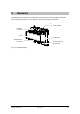
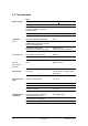
5.4 Interconnection
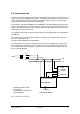
The P-bus connection of the link incorporates an internal DC power supply for 128 load units, to
supply the power for the DESIGO I/O modules. The DESIGO I/O modules are connected via the
P-bus connection using the P-bus coupling module (I/O bar type PTX 1.01). The main supply
voltage is derived from a separate AC 24 V transformer.
As described in data sheets CM2M8102 and CM2N8022. a double-insulated safety transformer
to EN 61 558, designed for continuous operation, must be used. At least conductor G must be
fused. The transformer must be sized for the effective load of the equipment in the control panel
including the connected field devices.
For separate control panel construction, please observe grounding precautions (as described in
CM2M8102).
To avoid earth loops, only G0 must be earthed to a central point. The earthing precautions for
the P-bus must be observed
(see data sheets CM2M8102 and CM2N8022).
For load distribution purposes, the G0 connection of the P-bus coupling module (I/O bar, type
PTX1.01) must be connected to G0 of the transformer. The G0 connection (between PU and
PC) of the DP/P-bus link is designed for connection of the P-bus/remote bus. The remote bus
has not yet been released.
230V~
P-bus
coupling
module
PTX1.01
G
G0
PU
PC
PD
DP/ P-bus link
Profibus
(9-pin DSUB, RS485)
G
G0
F1
F2
Ground
G G0 PU G0 PC PD
24V~
*
* Parallel connection of G0
(Terminal 2)
for connection of remote bus
not yet released.
Fig. 5-5: Overview of connections