
User Manual


PROFIBUS DP/P-bus link Siemens Building Technologies
5-6 User's guide Building Automation
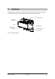
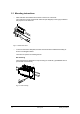
5.3 Connections
0
5
1
2
3
4
6
6
8
7
0
5
1
2
3
4
6
6
8
7
1
1 23
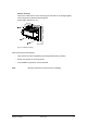
PTX1...
GG0Shield
G0PU PC PD
8
Profibus DP
Status ServiceAdress Profibus
x10 x1PS DP IO
DP/P-Bus Link
6FL6301-2FA01
Siemens Building Technologies AG
SELV 24 VAC
+
-
10% 60VA
50/60Hz T50°C IP20
x
2
HW
SW
Release
4765
3456789
23456789
x
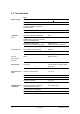
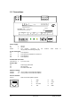
Power supply
G 1 AC 24 V
G0 2 Ground
Shield 3 The earthing connection for the Profibus cable shield is
not physically connected to ground (G0).
P bus connections
PU 4 P-bus signal PU
G0 5 P-bus ground in preparation for remote bus
PC 6 P-bus signal PC
PD 7 P-bus signal PD
Profibus DP connection
PROFIBUS DP 9 9-pin sub-D, RS485
Status LEDs
PS Power supply status LED
DP DP status LED
IO I/O module status LED
Address settings
Address x10 “Tens” position of the Profibus DP address
Address x1 “Units” position of the Profibus DP address
Service interface
Service RJ45 for firmware update if required
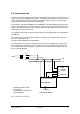
1
GND
5
VPP
2
RxD
6
CHM
3
Not used
7
BTL
1 2345678
4
TxD
8
GND