
User Manual


PROFIBUS DP/P-bus link Siemens Building Technologies
4-12 User's guide Building Automation
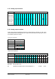
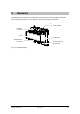
4.2.7 Interface modules WILO PTM50.16V01 / GRUNDFOS PTM52.16V01
As with the compact modules, these interface modules consist of a selection of individual mod-
ules accommodated together in a single housing. From the software viewpoint, a pump module
is handled in the same way as the equivalent individual module structure, and is displayed in
the same way in the SIMATIC Manager engineering tool.
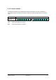
The basic P-bus address is set on the interface module by means of an address coding plug.
The address offsets for the individual modules are accounted for automatically (see the table
below). The user simply has to ensure that the offset address range is not used by other mod-
ules. The address coding on the other modules must be lower than the basic address and
higher than the basic address +13.
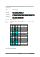
Compact modules are mapped to the SIMATIC memory in the order of their individual modules.
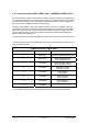
The WILO PTM50.16V01 and GRUNDFOS PTM52.16V01 interface modules comprise the fol-
lowing individual modules:
PTM50.16V01 and PTM52.16V01
Basic P-bus address + offset Individual module Remarks
+ 0 PTM1.2Y10
Channel 1: Switching command P1
Channel 2: Switching command P2
+ 1 PTM1.2Y10
Pump head setpoint P1
Pump head setpoint P2
+ 4 PTM1.2R1K
Normal operation code P1
Normal operation code P2
+ 5 PTM1.2R1K
Fault status code P1
Fault status code P2
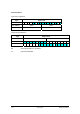
+ 8 PTM1.2R1K
Pump head P1
Pump head P2
+ 9 PTM1.2R1K
Pump volume P1
Pump volume P2
+ 12 PTM1.2R1K
Pump capacity P1
Pump capacity P2
+ 13 PTM1.2R1K
For more details, please refer to the data sheets for the pump modules (8663 and 8665).