
User Manual

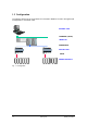
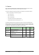
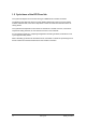
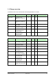

Table of contents
1 General...................................................................................................................... 1-1
1.1 Overview ................................................................................................................. 1-1
1.2 Application .............................................................................................................. 1-1
1.3 Configuration........................................................................................................... 1-2
1.4 Features.................................................................................................................. 1-3
1.5 Cycle times of the DP/P-bus link ............................................................................ 1-4
1.6 Range overview ...................................................................................................... 1-5
2 Engineering .............................................................................................................. 2-1
2.1 Importing the GSD file into the engineering tool..................................................... 2-1
2.2 Engineering the DP/P-bus link with the SIMATIC Manager ................................... 2-1
2.3 Modifying the DESIGO I/O configuration................................................................ 2-4
3 Diagnostics............................................................................................................... 3-1
3.1 Structure of slave diagnostics................................................................................. 3-1
3.1.1 Station status 1 .................................................................................................... 3-2
3.1.2 Station status 2 .................................................................................................... 3-3
3.1.3 Station status 3 .................................................................................................... 3-3
3.1.4 Master Profibus address...................................................................................... 3-4
3.1.5 Manufacturer identification................................................................................... 3-4
3.1.6 Code-based diagnostics ...................................................................................... 3-5
3.2 Diagnostics with LED indicators ............................................................................. 3-6
3.3 Diagnostics using the EMX block ........................................................................... 3-7
4 Module data .............................................................................................................. 4-1
4.1 Digital modules ....................................................................................................... 4-1
4.1.1 Digital input modules ........................................................................................... 4-1
4.1.2 Digital output modules ......................................................................................... 4-2
4.2 Analog modules ...................................................................................................... 4-3
4.2.1 Analog value display............................................................................................ 4-3
4.2.2 Analog measuring ranges.................................................................................... 4-5
4.2.3 Analog input modules .......................................................................................... 4-7
4.2.4 Analog output modules ........................................................................................ 4-7
4.2.5 I/O compact modules........................................................................................... 4-8
4.2.6 Status display unit PHM1.36TL ......................................................................... 4-11
4.2.7 Interface modules WILO PTM50.16V01 / GRUNDFOS PTM52.16V01............ 4-12
4.2.8 Counter modules ...............................................................................................4-13
5 Hardware .................................................................................................................. 5-1
5.1 Mounting instructions.............................................................................................. 5-2
5.2 Technical data......................................................................................................... 5-4
5.3 Connections ............................................................................................................ 5-6
5.4 Interconnection ....................................................................................................... 5-7
5.5 Dimension diagrams ............................................................................................... 5-8