
User Manual

PROFIBUS DP/P-bus link Siemens Building Technologies
3-6 User's guide Building Automation
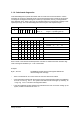
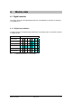
3.2 Diagnostics with LED indicators
The DP/P-bus link has three LEDs to indicate the status of the module.
• The DP LED lights up to indicate DP communications.
• The PU LED lights up during normal operation, provided that the internal power supply for
the DP/P-bus link is not overloaded.
• The IM LED uses various flashing sequences to indicate different types of fault. Each IM
module fault has a separate priority, so that if several IM faults occur, only the one with the
highest priority is indicated.
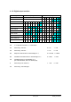
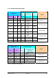
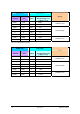
Error type DP
LED
PU
LED
IM LED flashing Priority
RAM test failed x x 1 (highest)
SPC3-RAM test failed x x
Frequency 0.5 Hz
2
Internal power supply overload x Off x
DP communications errors
Connection dropped Off x
No exchange of process images
(mapping)
Off x
Configuration error Off x
P-bus communications errors:
Connection dropped x x
Every 10 s for 3 s
(module scan: i.e. the
DP/P-bus link tries to
establish a connection
with the P-bus and/or
Profibus every 10
seconds).
3
x : Not relevant
During normal operation of the DP/P-bus link, the DP LED and PU LED remain on continuously.
The IM LED flashes rapidly. The flashing sequence slows down as the number of connected
DESIGO modules increases.