
User Manual

Siemens Building Technologies PROFIBUS DP/P-bus link
Building Automation User's guide 3-5
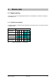
3.1.6 Code-based diagnostics
Code-based diagnostics provide the master with an overall view of which modules in a slave
assembly are currently in diagnostic mode. One bit is assigned to each module for this purpose.
The length of the diagnostic message is rounded up to byte limits, with any unconfigured bits
being filled with zeros. When a bit is set, this indicates that there is a diagnostic message in this
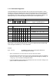
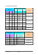
input/output range. The code-based diagnostics start at byte 6 and comprise 9 bytes.
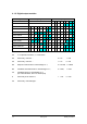
Byte 7 Bit 0 Description
6 0 1 0 0 1 0 0 1
Bits 7 and 6: Code-based diagnostics
Bits 5…0: Length = 9 (including byte 6)
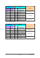
Byte 7 Bit 0 Description
7 8 7
6
5 4 3 2 1 Module 1 to 8
8 16 15 14 13 12 11 10 9 Module 9 to 16
9 24 23 22 21 20 19 18 17 Module 17 to 24
10 32 31 30 29 28 27 26 25 Module 25 to 32
11 40 39 38 37 36 35 34 33 Module 33 to 40
12 48 47 46 45 44 43 42 42 Module 41 to 48
13 56 55 54 53 52 51 50 49 Module 49 to 56
14
S
63 62 61 60 59 58 57 Module 57 to 63
Each number in the relevant bit field represents a module. A module which has caused a diag-
nostic message is identified by a “1” set in the bit field.
Example:
Byte 7, bit 5 set: The DESIGO module with the sixth-highest address has
caused a diagnostic message.
• There is no Module No. 64. This is where the common alarm bit is located.
• A new diagnostic message with the bit set is stored in the diagnostics buffer of the SIMATIC
S7 as an “incoming fault”. The system fault LED of the S7 CPU lights up. Similarly, an
“outgoing fault” is stored in the diagnostics buffer.
• If the same DESIGO module address was allocated more than once when setting up the
system, all bits in the bit field are set to “1”.