
User Manual


PROFIBUS DP/P-bus link Siemens Building Technologies
2-4 User's guide Building Automation
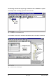
The DESIGO I/O modules already in position are listed, starting with Slot 1. The engineering
tool assigns the associated input and output addresses in accordance with the information in
the GSD file.
• Other modules can then be dragged from the list and dropped into the required slot. In
this process, it is important to ensure that the slots are filled without any gaps.
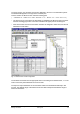
A maximum of 50 modules can be positioned in this way. Above this number, the engineering
tool rejects any further inputs. In the example shown, there are no other S7 modules, and there
is only one DP slave, giving a continuous sequence of input and output addresses.
However, if the overall system includes several DP slaves and additional S7 modules, the posi-
tioning of the modules can result in gaps in the address space of a given DP/P-bus link. This
depends on the order in which, for example, the individual DP slaves are configured with mod-
ules. In such cases, the engineering tool ensures that consistent data structures are transmitted
when data is exchanged.
On the P-bus side, there are no specific rules related to the positioning of the DESIGO I/O mod-
ules or their P-bus addresses.
However, when using the SIMATIC Manager for engineering, it is
important to ensure that the I/O modules are engineered in ascending order of their P-bus ad-
dresses.
2.3 Modifying the DESIGO I/O configuration
Note the following when modifying the hardware configuration:
• The addresses allocated in the engineering process must not be modified manually. This
makes the data structures inconsistent at transmission time, which can lead to unpredict-
able signal states at the outputs. It can also mean that the input signals are wrongly as-
signed.
• Similarly, modules must not be moved after they have been positioned in the list of module
slots, as the engineering tool does not automatically re-sort the address sequence.
• When modules are inserted later, the address range is not automatically adjusted to ac-
commodate them. This means that all the subsequent addresses have to be modified.
• If several links and additional modules are engineered, and the engineer wants to add an
additional module to one of the intervening links, the next unused address will be assigned
to this module. However, the engineering tool will ensure that the data is transmitted consis-
tently.