
User Manual


Siemens Building Technologies PROFIBUS DP/P-bus link
Building Automation User's guide 2-3
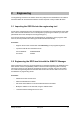
The power supply, CPU and DP/P-bus link are displayed in the form of a master/slave system.
The hardware list appears to the right of the hardware plan.
This list contains the DP/P-bus link under the following path:
( \ PROFIBUS-DP \Additional FIELD DEVICES\ I/O \ DESIGO I/O \ DP/P-bus-Link)
• The device can be connected to the DP master by highlighting the DP/P-bus link in the hard-
ware list and dragging the bus connection indicated in the upper pane of the dialog box.
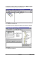
• Now click the DP/P-bus link to show which modules are assigned to which slots, and the I/O
addresses for that station.
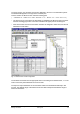
Fig. 2-3: DP/P-bus link module configuration
The modules are inserted into the appropriate slots in ascending P-bus address order, i.e. in the
order in which they were addressed on the P-bus side.
The input and output addresses for the automation station are allocated automatically in this
process. The address range of the DP/P-bus link must not overlap with the address range of
other bus subscribers.