
User Manual


Siemens Building Technologies PROFIBUS DP/P-bus link
Building Automation User's guide 2-1
2 Engineering
The engineering is based on the master device file (.GSD) which is standardized in accordance
with the Profibus DP and which describes the module response of every Profibus DP slave.
2.1 Importing the GSD file into the engineering tool
As part of the engineering process, the engineering tool needs to be informed about which GSD
file to use for the DP/P-bus link. This is normally done by importing the GSD file. (For the exact
path details refer to the description of the engineering tool.)
As a result of the import, the DP/P-bus link will appear as a field device in the program’s hard-
ware list, and the possible I/O module types will be selected automatically.
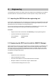
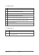
Procedure:
• Engineer the S7-CPU 3xx/4xx-2DP under HW-Config on the programming device.
• Import the GSD file from the DP/P-bus link
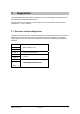
Current GSD file: SIEM80F6.GSD
ID number: 0x80F6
2.2 Engineering the DP/P-bus link with the SIMATIC Manager
When engineering a plant, the project engineering tool interprets the data in the GSD file for the
DP/P-bus link. It also runs plausibility checks to ensure that the engineering data is correctly
structured in terms of logic. When the engineering process is complete, the user can transfer
the combined engineering data from the DP/P-bus link and CPU 3xx/4xx-2DP to the CPU via
the SIMATIC S7 programming device.
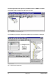
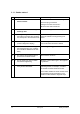
Procedure:
• Add DP/P-bus link as a DP slave.
• Select the DESIGO I/O modules
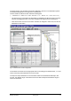
• Set the DP slave address on the associated DP/P-bus link module.
• Modify the address on the link itself, using the address switch.
• Load the hardware settings into the S7-CPU.