PROFIBUS DP/P-bus link User's guide Version 3.
Copyright: The software and this commissioning guide are protected by copyright. Multiple installation of the software is not permitted; the software license agreement, obtainable through Siemens Building Technologies must be complied with. All rights in respect of the user's guide are reserved, including those relating to reproduction and/or duplication in any form whatsoever, whether by photography or printing, or by transfer to any data medium, or by translation.
Table of contents 1 General...................................................................................................................... 1-1 1.1 Overview ................................................................................................................. 1-1 1.2 Application .............................................................................................................. 1-1 1.3 Configuration............................................................................
II PROFIBUS DP/P-bus link User's guide Siemens Building Technologies Building Automation
1 General 1.1 Overview The DP/P-bus link connects the DESIGO P-bus to the Profibus DP (“Distributed Peripherals”).This allows the direct exchange of data between DESIGO I/O modules and the SIMATIC S7 via Profibus DP. 1.2 Application The purpose of the DP/P-bus link is to connect two communications media, the P-bus and the Profibus DP, allowing access to the DESIGO I/O modules from a SIMATIC S7. Within the SIMATIC, the DESIGO I/O modules are treated as standard Profibus DP data points.
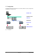
1.3 Configuration The following shows how the I/O modules are connected to SIMATIC S7 and to the higher-level management PC, SICLIMAT X-OS. SICLIMAT X-OS ETHERNET (TCP/IP) SIMATIC S7 PROFIBUS DP DP/P-Bus LINK P-BUS DESIGO IO Modules Fig.
1.4 Features On the P-bus side, the DP/P-bus link is enabled for the local bus (a P-bus cable up to 50m in length). On the Profibus side, distances of up to 1000m can be covered. The number of DESIGO I/O modules per DP/P-bus link depends on the following conditions: Maximum 50 DESIGO I/O modules are supported • Up to 128 load units • Max. 216 input bytes • Max.
1.5 Cycle times of the DP/P-bus link The cycle times depend on the number and type of DESIGO I/O modules connected. The DP/P-bus link takes less time to process digital modules than it does to process analog modules. With the latter, more time is required to convert the values into the format of the receiving device. The cycle time also depends on the number of channels of a module. Here too, more time is required for analog modules, as most of them have two or four channels.
1.6 Range overview The DP/P-bus link can be combined with the following DESIGO I/O modules: Digital In Load units Input bytes Output bytes PTM1.2D20 Digital input 2 x DI; potential-free contacts DC 22 V 2 1 0 PTM1.4D20 Digital input 4 x DI; potential-free contacts DC 22 V 1 1 0 PTM1.4D20R Digital input 4 x DI; open contact 1 1 0 PTM1.8D20E Digital input 8 x DI; potential-free contacts 1 1 0 PTM1.2D42 Digital input 2 x DI not electrically isolated; voltage signaling 2 1 0 PTM1.
Digital Out Load units Input bytes Output bytes Remarks PTM1.4Q250-P Pulse switching command; 2 single-stage consumers 2 1 1 Pulse modules must be operated by pulse switching commands from the SIMATIC. However, in order for the module to recognize the pulsed signal, it must be present for longer than one SICLIMAT cycle. PTM1.4Q250-P3 Pulse switching command; one 2-stage or 3-stage consumer 1 1 1 See PTM1.4Q250-P PTM1.
Analog Out Load units Input bytes Output bytes PTM1.2Y10S Analog output 2 x AO 0…10V 1 0 4 PTM1.4Y10S Analog output 4 x AO 0…10V 1 0 8 PTM1.2Y10S-M Analog output 2 x AO with manual operation; 0…10V 1 1 4 PTM1.2Y420 Analog output 2 x AO 4…20mA 1 0 4 PTM1.2Y250T Digital output 1 x DO; positioning modules, 3-position output 2 1 3 PTM1.2Y250T-M Digital output 1 x DO; with manual operation positioning modules with 3-position output 2 1 3 PTM6.
1-8 PROFIBUS DP/P-bus link User's guide Siemens Building Technologies Building Automation
2 Engineering The engineering is based on the master device file (.GSD) which is standardized in accordance with the Profibus DP and which describes the module response of every Profibus DP slave. 2.1 Importing the GSD file into the engineering tool As part of the engineering process, the engineering tool needs to be informed about which GSD file to use for the DP/P-bus link. This is normally done by importing the GSD file. (For the exact path details refer to the description of the engineering tool.
The following describes the engineering of a DP/P-bus link in a SIMATIC S7 system: The example shows an existing project with a CPU 315-2 DP. Fig. 2-1: SIMATIC S7-CPU hardware plan The “Hardware” object is then opened and the hardware plan for the station is displayed. Fig.
The power supply, CPU and DP/P-bus link are displayed in the form of a master/slave system. The hardware list appears to the right of the hardware plan. This list contains the DP/P-bus link under the following path: ( \ PROFIBUS-DP \Additional FIELD DEVICES\ I/O \ DESIGO I/O \ DP/P-bus-Link) • The device can be connected to the DP master by highlighting the DP/P-bus link in the hardware list and dragging the bus connection indicated in the upper pane of the dialog box.
The DESIGO I/O modules already in position are listed, starting with Slot 1. The engineering tool assigns the associated input and output addresses in accordance with the information in the GSD file. • Other modules can then be dragged from the list and dropped into the required slot. In this process, it is important to ensure that the slots are filled without any gaps. A maximum of 50 modules can be positioned in this way. Above this number, the engineering tool rejects any further inputs.
3 Diagnostics Code-based diagnostics are used for the DP/P-bus link. The LED display on the DP/P-bus link also indicates the overall operational status. Diagnostic data can be evaluated in the SICLIMAT X environment with the function module “DIAGNOSTIC I/Os” in the Emx. 3.1 Structure of slave diagnostics Profibus DP includes the option of processing diagnostic requirements based on error states.
3.1.
3.1.2 Station status 2 Bit Description 0 1: The DP/P-bus link parameters must be reset. 1 1: Diagnostic message received. The DP/P-bus link will not work until the fault has been cleared (static diagnostic message). 2 1: This bit is always set to “1”.in the DP/P-bus link. 3 1: Response monitoring is enabled in this DP slave. 4 1: The DP/P-bus link has received the control command “FREEZE”. This bit is only updated if another diagnostic message also changes.
3.1.4 Master Profibus address The “Master Profibus Address” diagnostic byte stores the Profibus address of the DP master, which • sets the DP/P-bus link parameters, and • has “read” and “write” access to the DP slave. The Master Profibus address is in byte 3 of the slave diagnostics. 3.1.5 Manufacturer identification The manufacturer’s identification includes a code which defines the type of DP slave.
3.1.6 Code-based diagnostics Code-based diagnostics provide the master with an overall view of which modules in a slave assembly are currently in diagnostic mode. One bit is assigned to each module for this purpose. The length of the diagnostic message is rounded up to byte limits, with any unconfigured bits being filled with zeros. When a bit is set, this indicates that there is a diagnostic message in this input/output range. The code-based diagnostics start at byte 6 and comprise 9 bytes.
3.2 Diagnostics with LED indicators The DP/P-bus link has three LEDs to indicate the status of the module. • The DP LED lights up to indicate DP communications. • The PU LED lights up during normal operation, provided that the internal power supply for the DP/P-bus link is not overloaded. • The IM LED uses various flashing sequences to indicate different types of fault. Each IM module fault has a separate priority, so that if several IM faults occur, only the one with the highest priority is indicated.
3.3 Diagnostics using the EMX block Field of application This module can be used to check module-specific faults in a DP/P-bus link. Description of functions • When a fault in the P-bus I/O modules occurs or is cleared, the DP/P-bus link triggers diagnostics function OB 82. OB 82 then calls system function SFC 13 to call up the diagnostics for the DP subscriber whose basic module address is “B-ADR”. • When the CPU starts up, it also calls system function SFC 13 for a diagnosis of the DP/P-bus link.
Diagram for graphics-based engineering DIAGNOSTIC I/Os Inputs Outputs Start addresses of modules ADDR.
4 Module data 4.1 Digital modules This section shows how the digital signals/channels of the DESIGO I/O modules are displayed in the SIMATIC S7. 4.1.1 Digital input modules The digital channels are displayed right-justified and in ascending order, so that the first channel is mapped to Bit 0. Type MSB LSB Input byte PTM1.2D20 0 0 0 0 0 0 i2 i1 PTM1.4D20 0 0 0 0 i4 i3 i2 i1 PTM1.4D20R 0 0 0 0 i4 i3 i2 i1 PTM1.8D20E i8 i7 i6 i5 i4 i3 i2 i1 PTM1.
4.1.2 Digital output modules Type MSB LSB Input byte MSB Output byte PTM1.2Q250 None x x x x PTM1.2Q250B None x x x x x x LSB o2 o1 a2 e2 a1 e1 PTM1.2QD 0 0 0 0 0 0 0 c1 x x x x x x x PTM1.4QD 0 0 0 0 0 0 c2 c1 x x x x x x o2 o1 PTM1.2Q250-M 0 0 h2 h1 k2 k1 0 0 x x x x x x o2 o1 PTM1.2QD-M 0 0 0 h1 0 k1 0 c1 x x x x x x PTM1.4QD-M2 0 0 h2 h1 0 k1 c2 c1 x x x x x x PTM1.
4.2 Analog modules The DESIGO I/O range incorporates various analog modules for the connection of sensors and/or loads/actuators. The following describes the principles of the SIMATIC S7 analog value display and the display of DESIGO analog values in the format required by SIMATIC S7. 4.2.1 Analog value display The digitized analog value is the same for input and output values in the same nominal range. The analog values are displayed in two’s complement format.
The table below shows how analog values are displayed by the analog modules: Resolution Analog value Bit number 15 14 13 12 11 10 9 8 7 6 5 4 3 2 1 0 Bit value VZ 214 213 212 211 210 29 28 27 26 25 24 23 22 21 20 8-bit resolution VZ 0 0 0 0 0 0 0 1 x x x x x x x 9-bit resolution VZ 0 0 0 0 0 0 0 0 1 x x x x x x 10-bit resolution VZ 0 0 0 0 0 0 0 0 0 1 x x x x x 11-bit resolution VZ 0 0 0 0 0 0 0 0 0 0 1 x x x x 12
4.2.2 Analog measuring ranges Voltage/current measuring range SIMATIC S7 PTM1.2U 10 PTM1.2I25 PTM1.2I42 0 Measured value in % Decimal Hex.
SIMATIC S7 Decimal PTM1.2P100 Hex. Ohms L&S Ni1000 standard range in °C (1 digit = 0.1 K) 32767 7FFF >408.1 3874 F22 408.1 3873 F21 250 408 600 258 123.24 60 0 0 100 0 -2582 F5EA 0 -234 -2581 F5EB -233.9 -32768 8000 <-233.9 Range Overflow, error Nominal range Overflow, error Tab. 4-4: Pt100 measuring ranges SIMATIC S7 Decimal Hex. PTM1.2P1K Ohms L&S Pt1000 standard range in °C (1 digit = 0.1 K) 32767 7FFF >408.1 3874 F22 408.
4.2.3 Analog input modules Type Input word PTM1.2R1K PTM1.4R1K PTM1.2P100 PTM1.2P1K A15 A14 A13 A12 A11 A10 A9 A8 A7 A6 A5 A4 A3 A2 A1 A0 PTM1.2U10 PTM1.2I25 PTM1.2I420 4.2.4 Analog output modules Analog output values are displayed in the form of a word value to a resolution of 11 bits. In the case of modules with manual operation, the output word is preceded by an input byte in which the feedback signals are mapped. Input byte comparison: Type Input byte PTM1.2Y10(S) None PTM1.
For PTM1.2Y250T(-M), manual operation is mapped in an input byte. The output value consists of 3 bytes, where the first two bytes display the output value as “word” and the runtime as a “Byte” data type. PTM1.2Y250T(-M) Type Input Byte 0 Output Word 0 Output Byte 0 0 0 0 0 k1 0 0 A14 A13 A12 A11 A10 A9 0 0 0 L3 L2 L1 A8 A7 A6 A5 A4 A3 A2 A1 A0 L0 A0 ... A14 Analog output value kx Feedback AUT/HND mode for Channel/Stage No. x; L0 ...
A compact module consists of a selection of individual modules accommodated together in a single housing. From the software viewpoint, a compact module is handled in the same way as the equivalent individual module structure, and is displayed in the same way in the SIMATIC Manager engineering tool. A distinction is made between “real” module types (also available as single modules) and “virtual” module types (implemented only in the software).
Virtual modules: Input word comparison: Type PTK1.12D20 Input word 0 0 0 0 i12 i11 i10 i9 i8 i7 i6 i5 i4 PTK1.8Q250 None None PTK1.11Q250 None None i3 i2 i1 Output word comparison: Type Output word PTK1.12D20 None PTK1.8Q250 o8 o7 o6 o5 o4 o3 o2 o1 PTK1.
4.2.6 Status display unit PHM1.36TL Up to 24 LEDs and 12 buttons on thePHM1.36T can be made to respond via the P-bus. A single key press provides a process signal to the SIMATIC for approximately 4 seconds, after which the signal is reset (behaves like an “acknowledge” key). PHM1.
4.2.7 Interface modules WILO PTM50.16V01 / GRUNDFOS PTM52.16V01 As with the compact modules, these interface modules consist of a selection of individual modules accommodated together in a single housing. From the software viewpoint, a pump module is handled in the same way as the equivalent individual module structure, and is displayed in the same way in the SIMATIC Manager engineering tool. The basic P-bus address is set on the interface module by means of an address coding plug.
4.2.8 Counter modules The PTM1.2C module has two independent counters each with a 7-bit value combined to a word. When using this module, note that the counter is a cyclical counter and that it cannot be reset. Type PTM1.
4-14 PROFIBUS DP/P-bus link User's guide Siemens Building Technologies Building Automation
5 Hardware The DP/P-bus link consists of a housing base, a housing cover and the printed circuit board with connection terminals. The unit also has a service socket and service LEDs. 80048 A Cable restraints Connection terminals Cover Housing base PROFIBUS DPconnection Servicesocket and Service-LEDs Fig.
5.1 Mounting instructions • Cable restraints are essential for the wires to the AC 24 V terminals. The conductors must be secured with cable ties (see diagram) to the lugs provided for this purpose on the base unit. 80170 Fig. 5-2: Cable strain relief • To ensure that heat is dissipated, the DP/P-bus link must be installed horizontally as shown in the diagrams below.
Surface mounting There are four drill holes for screw mounting (see “Dimensions” for drilling diagram). The housing base is fitted with raised supports. Screws: Max. diameter 3.5 mm 80061 Fig. 5-4: Surface mounting When mounting note the following: • There must be a means of dissipating the heat generated during operation. • Ensure easy access for service purposes. • Local installation regulations must be observed. Note Mounting instructions are printed on the packaging.
5.2 Technical data Type Operating voltage AC 24 V + 10% Frequency 50/60 Hz Power consumption of DP/P-bus link including DESIGO I/O modules (128 load units) 60 VA Internal fuse protection None Interfaces Protection standard to EN 60529 IP20 P bus See data sheets for the process bus (CM2N8022E) and the I/O modules and P-bus (CM2M8102D) Max.
Product safety CE conformity Dimensions See dimension diagrams Weight As per EMC directive 89/336/EEC, and low-voltage directive 73/23/EEC Width in DIN modular spacing units 8.5 Including packaging 0.
5.3 Connections 1 23 G G0 Shield SELV 24 VAC + - 10% 60VA 50/60Hz T50°C IP20 4 5 6 7 PU G0 PC PD PTX1... DP/P-Bus Link Release 6FL6301-2FA01 Siemens Building Technologies AG Profibus DP 8 HW SW Status PS DP x 2 3 4 5 6 7 8 9 x 2 3 4 5 6 7 8 9 Adress Profibus IO x10 6 1 1 7 8 6 0 7 8 6 2 3 4 5 6 2 3 4 5 1 Service x1 0 Power supply G G0 Shield 1 2 3 AC 24 V Ground The earthing connection for the not physically connected to ground (G0).
5.4 Interconnection The P-bus connection of the link incorporates an internal DC power supply for 128 load units, to supply the power for the DESIGO I/O modules. The DESIGO I/O modules are connected via the P-bus connection using the P-bus coupling module (I/O bar type PTX 1.01). The main supply voltage is derived from a separate AC 24 V transformer. As described in data sheets CM2M8102 and CM2N8022. a double-insulated safety transformer to EN 61 558, designed for continuous operation, must be used.
5.5 Dimension diagrams (All dimensions in mm) 62 110 90 35,3 80054 A 3,9 1 Fig. 5-6: Dimensions 100 80056 135 Fig.
Siemens Building Technologies AG Building Automation Gubelstr. 22 CH-6301 Zug Tel.