
User Manual


Fire Safety
53
Building Technologies 049_Archives_and_Libraries_A6
V10271399_a_en.doc
Fire Safety & Security Products 03.2009
All inert gas systems typically develop extinguishing agent concentrations of 40%
to 50% by volume. This means that the extinguishant occupies after the discharge
40% to 50% of the volume of the enclosure.
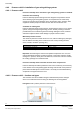
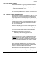
To vent the air displaced by
the extinguishant and to pre-
vent excess pressure from
being built up which would
damage the enclosure, the
volume of air displaced =
the volume of extinguishant
discharged
The size of the pressure
relief vent is calculated as a
FREE VENT AREA. This is
based on the maximum
pressure which can be with-
stood by the weakest part of
the enclosure. The weaker
the enclosure, the bigger the
required free vent area, the
stronger the enclosure, the
smaller the free vent area
Fig. 23 Vent area
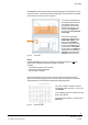
NOTE:
The free vent area given by the hydraulic flow calculation program is not
the
physical size of the hole required to be made in the wall!
Consider:
– Vent efficiency (typically 45% to 85%)
– External louvres and back-flaps
– Any ductwork in between.
All these listed above and many other restrictions will reduce the free area m
2
given in the calculation program, the vent size must be increased to compensate
and guarantee the correct pressure relief during discharge phase.
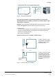
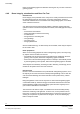
For a vent of 250mm x 250mm, the free
vent area @ 100% efficiency = 0.25 x 0.25
= 0.0625 m2
At an operating pressure of 300 Pa this flap
type is 38% efficient
Free vent area at 300 Pa = 0.0625 x 0.38 =
0.0238 m2
Fig. 24 Pressure relief