
User Guide

Document No.129-335
Installation Instructions
June 22, 2005
VE0268R1
1
2
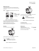
Figure 2. Mounting the Actuator on a Valve.
The installation is now complete.
Removing the Actuator from a Valve
1. Disconnect the wiring.
2. Unscrew actuator-coupling piece from the valve body
threads.
3. Remove the actuator from the valve.
Wiring
• All wiring must conform to NEC and local codes and
regulations.
• Use earth ground isolating step-down Class 2
transformers.
NOTE: Do not use autotransformers.
• Determine the supply transformer rating by summing
the total VA of all actuators used. The maximum
rating for a Class 2 step-down transformer is 100 VA.
NOTE: It is recommended that one transformer power
no more than 10 actuators.
• SFA71U/SFP71U 24 Vac actuators: Wiring
connection can be made inside the actuator housing
(remove the housing top for access).
• Line voltage actuators: Wiring connection requires
junction box and flex conduit no further than
15 inches (381 mm) from actuator.
G
G0
(Red)
(Black)
24 Vac
Neutral
EA0993R2
CAUTION:
G0 and G must be properly wired for correct
function and full life of the actuator.
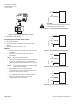
Figure 3. 24 Vac Actuator Wiring Diagram.
L
N
(Black)
(White)
120 Vac
Neutral
(Green)
GND
EA1036R2
Figure 4. 120 Vac Actuator Wiring Diagram.
L
N
(Red)
(White)
208 Vac
208 Vac
(Green)
GND
EA1140R1
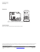
Figure 5. 208 Vac Actuator Wiring Diagram.
L
N
Neutral
(Blue)
(White)
277 Vac
(Green)
GND
EA1139R1
Figure 6. 277 Vac Actuator Wiring Diagram.
Page
2 of 4 Siemens Building Technologies, Inc.