
Install Instructions

Technical Instructions 599 Series Zone Valve Actuator
Document No. 155-321P25 SF Series Electronic Valve Actuator
January 30, 2008 2-position Control
Page 4 Siemens Building Technologies, Inc.
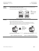
Wiring
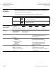
G
G0
(Red)
(Black)
24 Vac
Neutral
EA0993R2
Figure 2.
24 Vac Wiring Diagram.
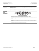
L
N
(Black)
(White)
120 Vac
Neutral
(Green)
GND
EA1036R2
Figure 3.
120 Vac Wring Diagram.
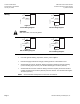
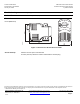
L
N
(Red)
(White)
208 Vac
208 Vac
(Green)
GND
EA1140R1
Figure 4.
208 Vac Wiring Diagram.
L
N
Neutral
(Blue)
(White)
277 Vac
(Green)
GND
EA1139R1
Figure 5.
277 Vac Wiring Diagram.
• Do not use autotransformers.
• Use earth-ground isolating, step-down, Class 2, power supplies.
• Determine supply transformer rating by summing total VA of all actuators used.
• SFA71U/SFP71U 24 Vac actuators: Wiring connection is inside the actuator housing
(remove housing top for access). The actuator lead length is 6 inches (152 mm).
• SFA11U/SFP11U 120 Vac actuators: Wiring connection requires junction box and flex
conduit no further than 15 inches (381 mm) from the actuator. The actuator lead length is
18 inches (457 mm).
NOTE: One transformer should power no more than 10 actuators.
WARNING:
Wire connection, G is Hot, not ground.