
Air Conditioner User Manual

SED2 VFD Electronic Bypass Option Operating Instructons
54 Siemens Building Technologies, Inc.
Programmable Output, NO
COM
NC
VFD Fault, NO
COM
NC
Drive Select, COM
NO
Bypass Select, COM
NO
Bypass Running, COM
NO
Overload Fault, COM
NO
DIGITAL
OUTPUTS
DIGITAL
INPUTS
DIP Switch
KEYPAD INTERFACE
VFD INTERFACE
HIGH VOLTAGE
CONTACTOR
CONTROLS
HIGH VOLTAGE/
120V
STEP-DOWN
POWER
TRANSFORMER
VFD Bypass
STOP
RESET
Input
On/Off
Enable
Input
Contactor
Output
Contactor
Bypass
Contactor
Overload
Relay
VFD
Hand
Start
Remote
Start
INTERLOCK START LOGIC
Enable Commanded Proofed
Auto Bypass Enabled
Essential Services
VFD Fault
Safety Fault
Overload Fault
Motor
J4
J5
J7
ON
OFF
MCU
TRANSFORMER
CONTROLLER
BOARD
SW1
F1
J3
J8
J2
J1
J6
13
14
15
16
17
18
19
20
21
22
23
24
25
26
1
2
3
4
5
6
7
8
9
10
11
12
VFD DO#1, NO
COM
VFD DO#2, NO
COM
VFD DI#1
Isolated 0V
VFD DI#2
VFD DI#3
Remote Start Input
Remote Safety #1
Remote Safety #2
Interlock Start
Essential Services
Overload Trigger
Input Contactor
ISO_IN6A
Output Contactor NO
ISO_IN6B
Bypass Contactor NO
Not Used
Output Contactor NC
120V Neutral
Bypass Contactor COM
120V Neutral
120V Hot
120V Neutral
120V Hot
120V Neutral
Ribbon Cable for Keypad
Pushbuttons and Indicators
INPUT
CONTACTOR
BYPASS
CONTACTOR
OUTPUT
CONTACTOR
MOTOR
8 9 10 11 12 13 14
76543 12
1
123
Earth Ground
120V Neutral
120V Hot
SED2
VFD
5
8
28
6
25
24
22
21
VFD DI#3
VFD DI#2
Isolated 0V
VFD DI#1
COM
VFD DO#2, NO
COM
VFD DO#1, NO
SED2 Relay
SED2 Fault
Remote Start/Stop
FUSE
INPUT DEVICE
OF VFD WITH
ELECTRONIC BYPASS
CUSTOMER
SUPPLIED
3-PHASE
POWER
Interlock Start Confirm
OK to Run
8
9
7
6
5
4
3
2
10
NOTE:
3-Contactor
Keypad
Shown.
Basic Sanity Test LED
Factory Use Only
Override Jumper
F2
FUSE
F3
FUSE
F4
VFD0122R2
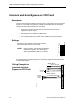
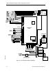
Figure 15. Controller Board Inputs and Outputs.