
Air Conditioner User Manual

SED2 VFD Electronic Bypass Option Operating Instructions
12 Siemens Building Technologies, Inc.
Electrical Installation
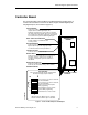
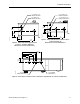
See Figure 9 for all Electronic Bypass Option wiring.
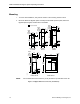
1. Route shielded twisted pair (recommended wire type) cable, 24 gauge minimum control
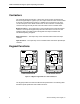
wiring in conduit through knockout and into housing (Figures 10 through 12). Connect
control wiring per job-specific drawings.
NOTES:
• Terminate shield at control device.
• Control wiring is 12 to 26 AWG and tightening torque is 5 lb-in.
2. If applicable, route communications wiring (P1) in conduit through knockout and into
housing (Figures 10 through 12). Continue to route communications wiring to SED2 and
terminate per SED2 VFD Startup, Operation, and Maintenance Manual (125-3201).
3. Route motor wiring in conduit through knockout and into housing (Figures 10 through 12).
Connect motor wiring to motor overload and ground lug. See Tables 1 through 4 for wire
sizes and tightening torques.
4. Route input power wiring in conduit through knockout and into housing (Figures 10
through 12). Connect input power wiring to disconnect switch and ground lug or to circuit
breaker and ground lug. See Tables 1 through 4 for wire sizes and tightening torques.