
Data Sheet for Product


6/16
Building Technologies Fan-coil controller for wall mounting ACR12 CE1N3578en
HVAC Products 03.10.2005
Window Contact Input
The window contact input (DU1, GND) is used to switch the operating mode from nor-
mal mode (defined by P01) to reduced mode (defined by P02). The idle position of the
contact is defined by P03.
The window contact input is separated from 230V and is SELV (Secure Electric Low
Voltage). No additional power supply is needed for detecting the position of the external
contact (the current necessary is delivered by the controller).
Several contacts can be wired serially and up to 30 controllers can be connected to
these contacts. Make sure that GND is connected with GND and DU1 with DU1 of
the different controllers. The maximum cable length should not exceed 250m.
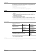
Since the currents of the individual inputs sum up, the diameter of the wires must care-
fully be chosen. If the diameter of the wires in the cable is below 1 mm
2
, then the follow-
ing graph shows the relationship between cable length, number of units connected in
parallel and the wire diameter.
0
5
10
15
20
25
30
0 50 100 150 200 250 m
1.00 mm
2
0.750 mm
2
0.50 mm
2
0.36 mm
2
0.25 mm
2
0.14 mm
2
0.08 mm
2
16 controllers are switched in parallel and the wire diameter is 0.25 mm
2
, then the
maximum cable length must not exceed 110 m. However with wire diameters of 0.75
mm
2
250 m are possible with up to 21 controllers.
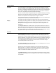
Circuit with normally closed contacts.
(Parameter P03 = ON or 1)
Circuit with normally open contacts.
(Parameter P03 = OFF or 0)
GND DU1
ACR12.4xx
Nbr. 1
Window
Contact
Nbr. 1
GND DU1
ACR12.4xx
Nbr. 2
Window
Contact
Nbr. 2
GND DU1
ACR12.4xx
Nbr. 3
Window
Contact
Nbr. 3
GND DU1
ACR12.4xx
Nbr. 1
Window
Contact
Nbr. 1
GND DU1
ACR12.4xx
Nbr. 2
Window
Contact
Nbr. 2
GND DU1
ACR12.4xx
Nbr. 3
Window
Contact
Nbr. 3
Settings
Security
Wiring Controllers
Example of wiring
Wiring diagrams
Number of controllers
Maximum cable length