
Data Sheet for Product


12/16
Building Technologies Fan-coil controller for wall mounting ACR12 CE1N3578en
HVAC Products 03.10.2005
Project engineering
and wiring notes
• Wiring, fuses and earthing must be installed in compliance with local regulations.
It must be made certain that safety extra low voltage lines (SELV circuits) are clearly
separated from AC 230 V mains voltage cables
(also refer to Installation Instructions G3573X)
• The cables to the controller, external sensor, fan, valves and to the electric heater
carry AC 230 V and must be appropriately dimensioned.
• Only sensors and valves rated for AC 230 V may be used
• The 230V mains power supply line must have an external fuse or circuit breaker with
a rated current of not more than 10 A. This means that the total load connected to
the controller (e.g. fan, electric heater) must be below 10 A.
• The controller is designed for withstanding overload currents which can occur in
connection with defective loads or wiring and which can be quite high before the fuse
in the 230V supply line (max. 10 A) interrupts the current.
• The connecting wires inside the controller must be placed so that no pressure is
exerted on components when the cover of the controller is closed
(also refer to Installation Instructions G3573X).
• The outputs to the fan motor are micro interruptions only. This means, that in error
cases more than one output can be switched on the same time. If this happens, the
short circuit current between two windings of the fan motor (and therefore two
outputs) can be essentially greater than the maximum allowed 10 A, due to the
special build of the fan motors. This short circuit current of two (or even three)
windings is not protected by the fuse in the supply line of the controller. Therefore it
must be either clear (verified through tests) that the erroneous currents are below
10 A or an (external) over-current protection must be installed in the connection lines
of the fan motor.
• If an electric heater is used, it must be protected against overheating by an inde-
pendent thermal switch or thermal fuse installed directly into the supply lines to the
heater (see also EN 60 335-2-73)
• The switching contacts for signal inputs must be suited for low power.
• The changeover inputs of different controllers must not be connected in parallel. This
means, one switching contact must be used per input. Remember that this input is
not isolated from 230V.
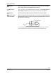
The controller is not approved for mounting on metallic surfaces unless the sur-
face is permanently connected to a protective conductor.
Important