
User Manual

6/6
Siemens RXT20.1 – Service terminal CA2N3851en_03
Building Technologies 2015-12-23
1
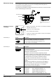
3206Z01
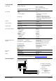
2 3 4 5 6 7 8
1 L
ON
W
ORKS
® -Bus (Desigo RXC): CLA; EIB-Bus (Desigo RCB): CE+
2 LONWORKS® -Bus (Desigo RXC): CLB; EIB-Bus (Desigo RCB): CE–
3 Not used
4 Not used
5 Not used
6 Not used
7 CP+ PPS2 data
8 CP– PPS2 data
The same pin layout applies to the tool socket.
The built-in connecting cable with an RJ45 connector is used to connect the service
terminal to the tool socket of a Desigo RXB / RXC controller, or to a QAX… room unit.
The service terminal communicates with the controller via the PPS2 interface.
Additionally, the bus is looped through the service terminal. RXC: this enables a PC for
the RXT10 service tool to be connected to the tool socket of the service terminal.
For correct operation of the service terminal, there must always be a room unit
connected to the controller. PPS2 communication is not possible without a room
unit.
1
2
80443 A
-
+
Auto
-
+
Auto
3
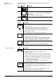
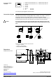
Options for connecting the RXT20.1 service terminal:
1 To QAX… room unit
2 To RXC… room controller
3 Not possible without QAX... !
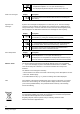
9,5
32
34
4,2
60
80088
90
100
56
60
56
Published by:
Siemens Switzerland Ltd.
Building Techno
logies Division
International Headquarters
Gubelstrasse 22
6301 Zug
Switzerland
Tel. +41 41
-724 24 24
www.siemens.com/buildingtechnologies
© Siemens Switzerland Ltd 2000
Delivery and technical specifications subject to change
Pin layout of RJ45
connector
Connection diagram
Caution:
Dimensions
All dimensions in mm