
User Manual

2/6
Siemens RXT20.1 – Service terminal CA2N3851en_03
Building Technologies 2015-12-23
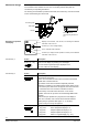
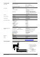
Essentially, the service terminal consists of the housing, the base plate and the cable
for connection to the controller or room unit. The housing and the base plate are
connected by a snap-fitting mechanism.
The housing accommodates a printed circuit board, the function keys, LCD and a socket
for the commissioning and service tool.
Connecting cable
Base plate
Housing
80444
80084
Socket for RXT10
commissioning and service
tool
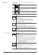
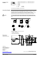
90044 A
Service -
Pin
Landis & Staefa
Error
Displays room unit status, “wink” function, error messages or additional
information of the room unit
Function key 1: Error message display
Cursor: Controller status indication
Function key 2: Displays remote operation of service pin and additional
information of the room unit
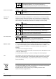
Action
Description
Press + or – key
Error
Press once to display any existing error messages.
The error with the highest priority is displayed for 5 s.
For error codes see “LCD display”
Action
Description
Press left key
Service
pin
The service pin is used to address the controllers when
commissioning the system.
– RXC: refer to the RXT10 user manual, document CA2110338
– RXB: refer to the ETS manual.
This function of the service terminal is especially useful for
addressing controllers in concealed locations where direct access
to the service pin is difficult. For this purpose, the service terminal
is connected to the room unit of the controller concerned.
Press this key on the left side for at least 1.5 s for remote
operation of the service pin of the connected Desigo RXB / RXC
controller.
While service-pin operation is in progress, the LCD display is
blank. The controller, room unit and service terminal will then
restart (ready for operation after approx. 3 – 5 minutes*)
* Varies according to the Desigo RX application
Press right key
1
st
key press Room temperature display in °C
2
nd
key press Room temperature display in °F
3
rd
key press Setpoint adjustment display in °C
4
th
key press Setpoint adjustment display in °F
5
th
key press Return to original display (e.g. “run”)
Mechanical design
Elements for operation
and display
Function key 1:
Function key 2: