
User Manual

7/16
Siemens RXL21.1, RXL22.1 Room controllers CM2N3877en_09
Building Technologies 2015-12-23
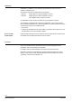
Disposal
The device is classified as waste electronic equipment in terms of the European Direc-
tive 2012/19/EU
(WEEE) and should not be disposed of as unsorted municipal waste.
The relevant national legal rules are to be adhered to.
Regarding disposal, use the systems setup for collecting electronic waste.
Observe all local and applicable laws.
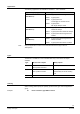
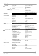
Engineering notes
Topology
Line or star
NO closed loops
Cable length
Max. 1000 m
Cable length
E.g. YCYM 2 x 2 x 0.8 mm
number of RXL Controllers per Network
Max. 45
Bus supply
Up to 45 RXL-controllers:
5WG1 125-1AB12
Bus terminator
Not required
The RXL2… room controllers operate with a supply voltage of AC 24 V.
The controlled devices (valves and damper actuators) receive their power directly from
the room controller. This means that a separate AC 24 V supply is not necessary for
the field devices.
This device has no circuit breakers for supply lines to external consumers (field power
supply)!
Line insulation must always be sufficient for the available rated voltage.
When forwarding supply voltage (for 24 V low voltage as well) to external consumers,
the wiring cross sections must at any rate be adapted to the preswitched overcurrent
protection device. Please comply under all circumstances with local regulations.
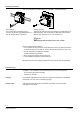
• The volt-free relay outputs allow the switching of loads up to AC 250 V, 5 A (4 A).
The heating coil relay in the RXL22.1 switches resistive loads up to 1.8 kW.
The cable dimensions depend on the connected load and the local installation
regulations.
• The circuits must be externally fused (≤ 10 A) as there are no internal fuses.
• The cables connected to the room controller must be secured with cable restraints.
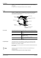
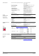
The fans must not be connected in parallel.
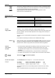
The simultaneous load on outputs Y1 … Y4 must not exceed 9.5 VA.
Y1 (heating) 2 thermic valve actuators, type STP73 5 W
Y2 (cooling) 2 thermic valve actuators, type STP73 5 W
Y3, Y4 (outside air) 3-position damper actuator 4.5 VA 4.5 VA
The maximum load is 9.5 VA for the heating sequence and 9.5 VA for the cooling
sequence.
This is acceptable because the two sequences never operate at the same time.
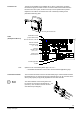
Bus
AC 24 V
supply cables
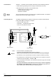
Caution
Volt-free
relay outputs
AC 230 V
AC 24 V triac outputs
Example: