
User Manual

5/16
Siemens RXL21.1, RXL22.1 Room controllers CM2N3877en_09
Building Technologies 2015-12-23
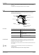
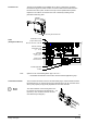
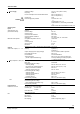
Terminal covers (RXZ20.1) are available as an option, to protect the connection
terminals from physical contact and dirt. The service LED remains visible when the
terminal covers are in place, and the service pin can be operated with a pointed
implement. The cable is connected to the room controller by breaking out the
perforated cable entry guide.
3873J02
Removing the terminal cover
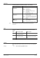
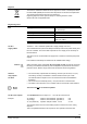
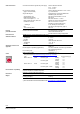
Identification number
(unique serial number)
ID in bar-code form, code 128
Protection standard
Temperature range
(0 … 50 °C)
Serial No.
Test date, series
(Z, A, B, C…)
Observe notes
in this document
Activated application
Location
3877Z04
010025CA9900
060215B 513
Options for use of the labeling fields “Appl.” and “Loc.”:
− Handwritten identification of the location and the activated application group.
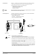
The connection terminals for the bus are detachable plug-in screw-terminals. All other
terminals are fixed. To avoid incorrect wiring, terminals which can be connected to AC
230 V (relay outputs) are physically separate from the other terminals.
The cable restraints on the housing base must
be used for the connections to terminals 22 … 28
(AC 230 V). The conductors must be secured
with cable ties (see diagram).
3877J04
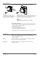
Terminal cover
Label
(example for RXL21.1)
Note
Connection terminals