
User Manual

4/16
Siemens RXL21.1, RXL22.1 Room controllers CM2N3877en_09
Building Technologies 2015-12-23
Compatibility
The RXL2… room controller is compatible with field devices from Siemens Building
Technologies.
For details, refer to the Desigo RX hardware overview, CA2N3804.
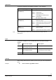
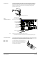
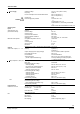
Design
The RXL2... controllers consist of a housing base, a housing cover and the printed
circuit board with connection terminals. The controllers also have a tool socket, a
service LED and a programming pin.
Con
nection
terminals
Housing cover
Connection
terminals
3873J01
Cable restraints
Plug-in connection terminals
for the bus
Housing base
Service LED
Programming pin
Tool socket
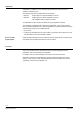
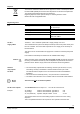
The programming LED shows the operational status of the room controller as follows:
Green flashing
OK, device is in operation
Red ON
• Addressing mode (ACS / ETS)
• Fault
Orange / green flashing
Parameter download
OFF
• No supply voltage
• Fault
• Service LED disabled by software
Other patt
erns • Start-up (approx. 5.sec)
• Fault
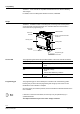
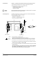
The programming pin is used to identify the controller in the commissioning phase.
Pressing this pin causes the red programming LED to light up and remain on until
identification of the controller is complete.
Once the service pin has been pressed, the tool overwrites the hardware address in the
room controller.
If there are no terminal covers fitted, the service pin may be operated only by a
qualified electrician.
The adjacent terminal may be a live mains voltage conductor.
Service LED
Programming pin