
User Manual


12/16
Siemens RXL21.1, RXL22.1 Room controllers CM2N3877en_09
Building Technologies 2015-12-23
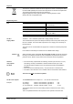
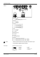
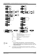
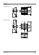
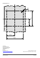
Connection terminals
3877A09
17 18
Bus
12 4 3
QAX...
T
M
25 26 27 28
Q13
Q14
Q24
Q34
AC 230V 5(4)A
22 23
24
Q43
Q44
AC 230V 10A
19 19 21 21
M
D1
GND
D2
Y1
G
Y2
CP –
CP +
CE
–
CE +
B1
1 2 3 4 5 6 7 8 9 13 14 15 1610 11 12
N.C.
N.C.
N.C.
N.C.
CE
–
CE +
N.C.
G0
G
G0
G
AC 24 V
SELV / PELV
Measured value input
B1
1
Measured value input for LG-Ni 1000 sensors
M
2
Measured value input ground
Signal inputs
D1
4
Signal input
GND
5
Signal ground
D2
6
Signal input
Triac outputs
Y1
7
AC 24 V, 0.5 A switching output
G
8
AC 24 V actuator supply
Y2
9
AC 24 V, 0.5 A switching output
Room unit
CP–
13
PPS2 ground
CP+
14
PPS2 data
CE+
15
Bus
CE–
16
Bus
Bus (plug-in connection)
CE+
17
Bus
CE–
18
Bus
Power supply
G0
19
Controller ground
G
21
AC 24 V +/- 20 %
Relay outputs
Q13
25
Common feed for Q14, Q24 and Q34
Q14
26
Normally-open contact, max. AC 250 V, 5 (4) A (Stage 1)
Q24
27
Normally-open contact, max. AC 250 V, 5 (4) A (Stage 2)
Q34
28
Normally-open contact, max. AC 250 V, 5 (4) A (Stage 3)
Q43
23
Lead wire for Q44
Q44
21
N/O contact AC max. 250 V, 10 A...(electric heating coil)
• Observe the technical data for the relay outputs: Max. AC 250 V, 5 (4) A and 10
A, respectively
• Local installation regulations must be observed.
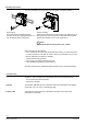
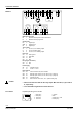
P
roprietary RJ45-type tool socket
1
3206Z01
2 3 4 5 6 7 8
1 Bus (CE+)
2 Bus (CE–)
3 Not used
4 Not used
5 +12VDC
6 RxD
7 PPS2 (CP+) / TxD
8 PPS2 (CP–)
RXL22.1
Caution
Tool socket