
User Manual


7/10
Siemens RXC40 – Extension module for lighting control CA2N3842en_06
Building Technologies 2015-12-23
Dimensions
See dimension diagrams
Width in DIN modular spacing units
4.5
Weight
Excluding packaging
0.25 kg
*) The documents can be downloaded from http://siemens.com/bt/download.
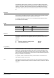
Connection terminals
16 17 18 19
N
Y2
–
Y
2+
250 V
12 A
80064
1 2 3 4 5 6
GND
D2
D3
GND
D
4
D1
15
Q24
14
Y1+
13
Y1–
1211
N
10
Q
14
98
N
7
Q13
DC 1...10 V
250 V
12 A
DC 1...10 V
PE
PE
PE
Signal input for volt-free momentary-contact switches
D1
1
Signal input
GND
2
Signal ground
D2
3
Signal input
D3
4
Signal input
GND
5
Signal ground
D4
6
Signal input
Relay outputs
Q13
7
Common contact for Q14 and Q24
N
8
Neutral conductor, max. AC 250 V
PE
9
Protective earth conductor
Q14
10
N/O contact AC max. 250 V, 12 A
N
11
AC 250 V neutral conductor
PE
12
Protective earth conductor
Q24
15
N/O contact AC max. 250 V, 12 A
N
16
Neutral conductor, max. AC 250 V
PE
17
Protective earth conductor
Control outputs
Y1–
13
Control output ground
Y1+
14
Control output DC 1...10 V external
Y2–
18
Control output ground
Y2+
19
Control output DC 1...10 V external
• Observe the technical data for the relay outputs: max. AC 250 V, 12 A
• Local installation regulations must be observed.
80052
G0
ADDRz
ATTNz
VCC
DG
G
RDY
DATA
CLK
DG
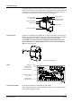
G0 Ground
ADDRz Module address
ATTNz Handshake
VCC DC 5 V
DG Electronics ground
G AC 24 V
RDY Handshake
DATA Data
CLK Clock
DG Electronics ground
STOP
Note!
Connector for
extension modules