
User Manual


5/10
Siemens RXC40 – Extension module for lighting control CA2N3842en_06
Building Technologies 2015-12-23
The control outputs are designed for control of dimmable electronic ballast units or
dimmable transformers. The current is supplied by the ballast unit or transformer.
The outputs are not suitable for controlled devices such as valve actuators with a
DC 0 … 10 V input.
The analogue output circuits are electrically isolated with 4 kV from the other module
electronics. It is therefore permissible to route the associated conductors in the same
cable as those for the switched AC 230 V connection.
If the control outputs are used, the AC 230 V must be connected to terminals Q13
(7) and N (8). The ballast unit must be connected and switched on when the 1...10 V
voltage is to be controlled. The 1...10 V control outputs are deemed to be mains
circuits and must be segregated from the SELV / PELV in the same way as AC
230 V cables.
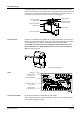
Mounting
The RXC40 extension module is mounted together with the RXC30 / RXC31 / RXC38
basic module and any additional extension modules on a DIN rail (type EN50022-
35x7.5).
80114
When mounting, note the following:
• The controller should not be freely accessible after mounting
• Ensure adequate air circulation to dissipate heat generated during operation.
• Easy access is required for service personnel
• Local installation regulations must be observed.
The mounting instructions are printed on the controller packaging.
Commissioning
The notes in the technical documentation for the RXC30 / RXC31 / RXC38 controller
(data sheet 3840 / 3844 / 3841) apply equally to a combination comprising the RXC30 /
RXC31 / RXC38 and the RXC40 extension module.
• The module is not protected against accidental connection to AC 230 V on the
SELV / PELV side.
• Mains AC 230 V for the relays must be disconnected before plugging and un-
plugging the terminal blocks (danger of electric shock!)
DC 1...10 V
control outputs
STOP
Note!
STOP
Note!