
User Manual


4/10
Siemens RXC40 – Extension module for lighting control CA2N3842en_06
Building Technologies 2015-12-23
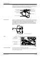
Cable restraints on the housing base must be used for
the wires to terminals 7 … 12 and 15 … 17
(AC 230 V). The conductors must be secured with
cable ties (see diagram).
3834J01
Ensure that the power is off before inserting or removing plug-in terminals
connected to a mains voltage.
The RXC40 extension module communicates via a serial bus connection (the PE bus)
with the basic controller RXC30 / RXC31 / RXC38. The PE bus connections are looped
through the module to the connection socket for the next extension module.
There is no direct connection to the L
ONWORKS® bus.
Disposal
The devices are classified as waste electronic equipment in terms of the European Direc-
tive 2012/19/EU
(WEEE) and should not be disposed of as unsorted municipal waste.
The relevant national legal rules are to be adhered to.
Regarding disposal, use the systems setup for collecting electronic waste.
Observe all local and applicable laws.
Engineering notes
The RXC40 can be used only in conjunction with an RXC30 / RXC31 / RXC38 basic
module (and possible additional extension modules). The plug-in connection between
the basic module and the extension modules incorporates both the communications
and the power supply. The power supply is limited to a maximum of two extension
modules.
The cables for signal inputs D1 … D4 (SELV / PELV) must be routed separately from
the AC230 V cables and must comply with SELV / PELV requirements. The low voltage
and mains voltage must not be routed in the same cable.
Only volt-free pulsed momentary-contact switches may be connected to the sig-
nal inputs.
The volt-free relay outputs may be used to switch filament lamps up to 2.5 kW or fluo-
rescent lamps up to 1.5 kVA. The cable dimensions depend on the connected load and
the local installation regulations. Neutral and protective conductors are looped on the
controller so that there is no need for external terminals. The circuits must be protected
with external fuses (max. 16 A, Q13) as there are no internal fuses. The cables must be
secured with a strain relief clamp.
STOP
Note!
Warning!
Communication
Signal inputs
Important
AC 250 V volt-free
relay outputs