
User Manual


5/12
Siemens RXC10 – Room controller CA2N3830en_06
Building Technologies 2015-12-23
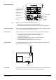
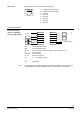
The service pin is used to identify the controller in the commissioning phase.
When the pin is pressed, the controller’s identification number is transmitted to the
RXT10 commissioning and service tool.
Disposal
The devices are classified as waste electronic equipment in terms of the European Direc-
tive 2012/19/EU
(WEEE) and should not be disposed of as unsorted municipal waste.
The relevant national legal rules are to be adhered to.
Regarding disposal, use the systems setup for collecting electronic waste.
Observe all local and applicable laws.
Engineering notes
The Desigo RXC installation guide, document CA110334, contains the relevant
engineering information for the L
ONWORKS® bus (topology, bus repeaters, bus
termination etc.) and for the selection and dimensions of connecting cables for the
supply voltage and field devices.
The controller operates with an AC 24 V supply voltage. Connected valves are supplied
directly from the controller.
This device has no circuit breakers for supply lines to external consumers (field power
supply)!
Line insulation must always be sufficient for the available rated voltage.
When forwarding supply voltage (for 24 V low voltage as well) to external consumers,
the wiring cross sections must at any rate be adapted to the preswitched overcurrent
protection device. Please comply under all circumstances with local regulations.
The simultaneous load on outputs Y1 and Y2 must not exceed 9.5 VA.
Example: Y1 (heating) 2 thermic valve actuators, type STP72E 6 W
Y2 (cooling) 2 thermic valve actuators, type STP72E 6 W
The maximum load is 9.5 VA for the heating sequence and 9.5 VA for the
cooling sequence. This is acceptable because the two sequences never
operate at the same time.
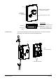
Mounting
The mounting instructions are printed on the controller packaging, together with a
drilling template.
The unit is not protected against accidental connection to AC 230 V.
Commissioning
The RXC10 controller is commissioned with the RXT10 commissioning and service
tool. For this purpose, the RXT10 is connected to the L
ONWORKS® bus via the tool
socket on the controller.
The commissioning procedure for the entire Desigo RXC range is described in detail in
the RXT10 user manual, document CM110669.
Service pin
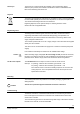
Caution
AC 24 V triac outputs
STOP
Caution!