
User Manual


4/12
Siemens RXC10 – Room controller CA2N3830en_06
Building Technologies 2015-12-23
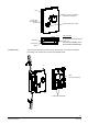
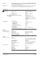
Bar code, Code 128
(Identification number
of Neuron chip)
Identification number
of Neuron chip
Test date, series
(Z, A, B, C…)
Preloaded application
(example)
Protection standard
Location
Definitive
application
loaded
Options for use of the labelling fields “Appl.” and “Loc.”:
− Hand-written entry of the location and the loaded application ... or
− Printed adhesive label (printed from the RXT10 commissioning and service tool)
The two rows of terminals are slotted into the housing base (see the diagram “Terminal
cover”). They can be removed to facilitate connection.
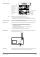
The RXC10 controller communicates with other devices via the following interfaces:
• LONWORKS® bus (terminals CLA and CLB) for communication with:
− PXR system controller or NIDES.RX interface (to Desigo)
− Other Desigo RXC devices
− LONMARK®-compatible 3
rd
party devices (e.g. presence detector)
• Tool socket (RJ45) on the controller, for:
− RXT10 commissioning and service tool (LONWORKS® bus)
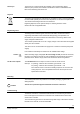
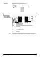
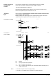
The following diagram shows the wiring of the L
ONWORKS® bus and interface to the
RXT10 commissioning and service tool.
3830A01
CLA
CL
B
LonWorks® Bus
Tool
LonWorks®
RXT10
LonWorks®
RXC10
The yellow service LED shows the current operational status of the controller by means
of different flashing patterns (see the RXT10 user manual, CM110669).
Label (inside housing)
Note
Connection terminals
Communication
LONWORKS® bus
Service LED