
User Manual


10/12
Siemens RXC10 – Room controller CA2N3830en_06
Building Technologies 2015-12-23
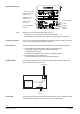
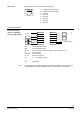
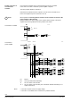
Up to 2 thermic actuators can be connected directly to the room controller.
In the case of more than 2 actuators a power amplifier is required.
The same principle applies to outputs Y2.
Note that the simultaneous load on outputs Y1 and Y2 must not exceed 9.5 VA.
Power consumption at input X1 of the UA1T: 0.5 VA.
Mixed operation: Connecting thermic actuators to the controller as well as to the
power amplifier is NOT allowed.
Differing voltage of the power supply of the controller and the supply of the power
amplifier may cause big differences in the position of the valves.
AC 24 V
00105 D
Y1
N1
Y1
G
G
G0
Y1.1
G
G0
1
2
3
4
NS
LS
COM
X1
AC 24 V
Y1.1
Y1.2
00105 E
Y1
8
7
6
5
COM
Y1
COM
Y1
N2
1
2
3
4
NS
LS
COM
X1
Y1.5
Y1.6
8
7
6
5
COM
Y1
COM
Y1
N2
G G0
Y1.3
Y1.4
Y1.7
Y1.8
N1
Y1
G
G G0
AC 24 V
G
G0
N1 RXC10
N2 UA1T (see data sheet CA2N3591)
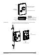
Y1 AC 24 V thermic valve actuator
Y1.1 AC 24 V thermic valve actuator (max. 2 STA72E / STP72E actuators per Y1
output on the UA1T)
• The UA1T requires an AC 24 V supply voltage
• The UA1T is not suitable for the connection of 3-position actuators.
Parallel connection of
several thermic
actuators
STOP
Note!
Connection to controller
Connection to
power amplifier
Notes