
User Manual

3 / 12
Siemens RXB39.1 – Room controller CM2N3875en_08
Building Technologies 2016-05-18
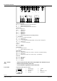
Technical design
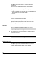
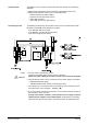
The RXB39.1 controller consists of a housing base, a housing cover and the
printed circuit board with connection terminals. The room controller also has a tool
socket, a service LED and a programming button.
Plug-in connection terminals
Cover
Plug-in connection terminals
80048
Cable restraints
Plug-in connection terminals
for KNX bus
Housing base
Service LED
Programming button
Tool socket
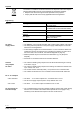
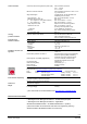
The Service LED shows the operational status of the room controller as follows:
Green, flashing
Normal operation.
Red, ON
• Programming mode for address assignment (ETS / ACS).
• Fault
Orange / green,
flashing
• Startup phase.
• No application selected.
• Loading.
− Download from ACS.
− Room unit QAX34.3 in HandyTool mode.
OFF
• No supply voltage
• Fault
Other patterns
After switching on the operating voltage, the service LED
flashes in different patterns for 3 to 5 seconds.
If other patterns appear during normal operation, this indicates
an error.
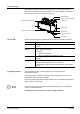
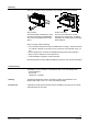
The programming button is used to identify the room controller in the
commissioning phase.
Pressing this button causes the red service LED to light up and remain on until
identification of the controller is complete.
Once the programming button has been pressed, the tool overwrites the hardware
address in the room controller.
If there are no terminal covers fitted, the programming button may be operated
only by a qualified electrician.
The adjacent terminal may be a live mains voltage conductor.
Service LED
Programming button