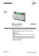
3 875 s RXB Room controller RXB39.1 Communicating room controller for fan-coil applications FC-13 The RXB39.1 room controller is used for temperature control in individual rooms.
Use The RXB39.1 room controller is optimized for control of fan-coil systems in individual rooms. The function of each controller is determined by the application software. The controllers are delivered with a fixed set of applications. The relevant application is selected and activated during commissioning using one of the following tools: • ETS Professional • "HandyTool" (the QAX34.
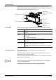
Technical design The RXB39.1 controller consists of a housing base, a housing cover and the printed circuit board with connection terminals. The room controller also has a tool socket, a service LED and a programming button.
Terminal cover Terminal covers (RXZ30.1) are available as an option, to protect the connection terminals from physical contact and dirt. The service LED remains visible when the terminal covers are in place, and the programming button can be operated with a pointed implement. The cable is connected to the room controller by breaking out the perforated cable entry guide.
Communication The RXB39.1 room controller communicates with other devices via the following interfaces: • PPS2 interface (proprietary) for the exchange of data with the room units • KNX bus (terminals CE+ and CE-) for communication with: − PX/KNX interface (to Desigo Insight) − Interface OCI700 / OCI702 (to Synco) − Other RXB controllers − Other KNX devices (e.g.
Disposal The device is considered an electronics device for disposal in terms of European Directive 2012/19/EU and may not be disposed of as domestic garbage. • Dispose of the device through channels provided for this purpose. • Comply with all local and currently applicable laws and regulations. Engineering KNX bus Topology Cable length Cable type Number of RXB Controllers per Network Bus supply Bus terminator Tree, line, or star NO closed loops Max.
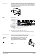
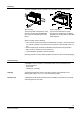
Mounting The room controllers can be mounted in any orientation, and fixed as follows: 80060 80061 Rail mounting The housing base is designed for snapmounting on DIN rails, type EN5002235x7.5 (can be released with a screwdriver) Surface mounting There are four drill holes for screwmounting (see “Dimensions” for drilling template). The housing base is fitted with raised supports. When mounting note the following: • The controller should not be freely accessible after mounting.
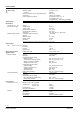
Technical data Power supply Operating data Inputs (SELV) Signal inputs D1 … D4 (for volt-free contacts) Measured value input B1 Outputs (SELV) DC 0 … 10 V YC1, YC2, YC3 Supply output G (SELV) Relay outputs Q34 (fan release) Q14 (heater release) Ports/interfaces Interface to room unit KNX bus Operating voltage Frequency Power consumption with connected field devices Internal fuse External supply line protection Control algorithm AC 230 V +/-10 % 50/60 Hz Max.
Cable connections Connection terminals for signals and power supply KNX bus connection terminals Single cable lengths Signal inputs D1 … D4 Measured value input B1, B2 0 … 10 V outputs YC1, YC2 (valve actuators) 0 … 10 V outputs YC3 (fan) Relay outputs Q14, Q34 Interface to room unit Cable type KNX bus Tool connecting cable Solid or stranded conductors 0.25 … 2.5 mm2 or 2 x 1.5 mm2 Solid or stranded conductors 2 x max. 1.0 mm2 e.g. YCYM 2x2x0.
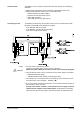
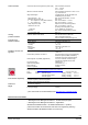
GND D2 D3 GND D4 3 19 19 21 21 Q34 Q33 Q14 23 24 25 26 27 G0 4 G 1 Q13 L L N N AC 230 V G0 2 Ni1000 0 ... 10 V YC1 24 ... 230 V 5(4) A 10 A T 3875A08 D1 CE + B2 17 18 CE – B1 10 11 12 13 14 15 16 0 ... 10 V YC3 9 CE + 8 CE – 7 0 ... 10 V YC2 6 CP + 5 AC 24 V 4 CP – 3 N.C. 2 N.C. 1 M Connection terminals KNX QAX...
Connection diagrams Connection of field devices, room unit, KNX bus and power supply G0 G G0 G N1 B1, B2 D1 … D4 Y1 Y2 Q1 Q2 Q3 B3 RXB39.1 LG-Ni 1000 temperature sensor Volt-free contacts (window contact, occupancy sensor, etc.) 0 … 10 V valve actuator heating 0 … 10 V valve actuator cooling (heating / cooling in case of changeover) Controlled fan Power controller (PWM or modulating) e.g. SEM61.4 + SEA45.1, data sheets N5102, N4937 Electric heating QAX… room unit Twisted pair For Q2 (1.8 kW max.
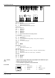
Dimensions (in mm) 3876M01 90 110 35,3 Without terminal covers 3,9 1 62 50 With terminal covers 62 120 35,3 6 3,9 1 161 3876M02 152 80056 100 Drilling diagram 135 Published by: Siemens Switzerland Ltd. Building Technologies Division International Headquarters Gubelstrasse 22 6301 Zug Switzerland Tel. +41 41-724 24 24 www.siemens.com/buildingtechnologies © Siemens Switzerland Ltd 2012 Delivery and technical specifications subject to change 12 / 12 Siemens Building Technologies RXB39.