
User Manual
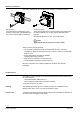
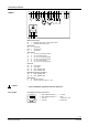
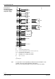

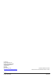
Table Of Contents
13 / 16
Siemens RXB24.1 – Room controller CM2N3874en_08
Building Technologies 2016-05-18
Up to two thermic actuators per sequence may be connected directly to the room
controller. With more than two thermic actuators, a UA1T power amplifier is
required.
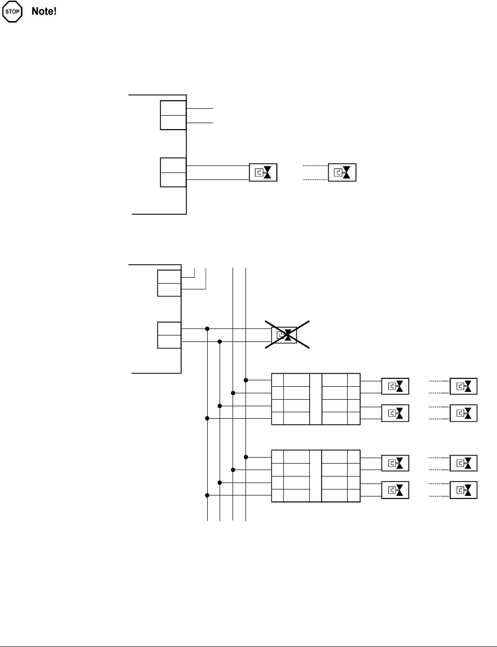
The principle is the same for output Y2. Do not exceed the maximum simultaneous
load on outputs Y1 and Y2 (max. 9.5 VA).
Power consumption at input X1 of the UA1T: 0.5 VA.
Mixed operation: It is not permissible to connect thermic actuators both to
the controller and to the power amplifier.
Owing to the difference in voltage between the controller's internal transformer and
the power supply of the UA1T, this could cause the valve positions to deviate
substantially.
AC 230 V
3873Z12
Y1
N1
L
N
Y1
G
L
N
Y1.1
1
2
3
4
NS
LS
COM
X1
AC 24 V
Y1.1
Y1.2
3873Z13
Y1
8
7
6
5
COM
Y1
COM
Y1
N2
1
2
3
4
NS
LS
COM
X1
Y1.5
Y1.6
8
7
6
5
COM
Y1
COM
Y1
N2
G G0
Y1.3
Y1.4
Y1.7
Y1.8
N1
L
N
Y1
G
AC 230 V
L
N
N1 Room controller RXB24.1
N2 UA1T power amplifier (see data sheet CA2N3591)
Y1 AC 24 V thermic valve actuators connected to the controller
Y1.x AC 24 V thermic valve actuators
(max. 2 STA73 / STP73 actuators per Y1 output on the UA1T)
– The UA1T requires an AC 24 V supply voltage
– The UA1T is not suitable for the connection of 3-position actuators.
Parallel connection
of several thermic
valve actuators
Connection to the
controller
Connection to the
power amplifier
Notes