
User Manual
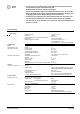
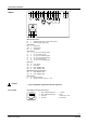
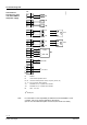

Table Of Contents
12 / 16
Siemens RXB24.1 – Room controller CM2N3874en_08
Building Technologies 2016-05-18
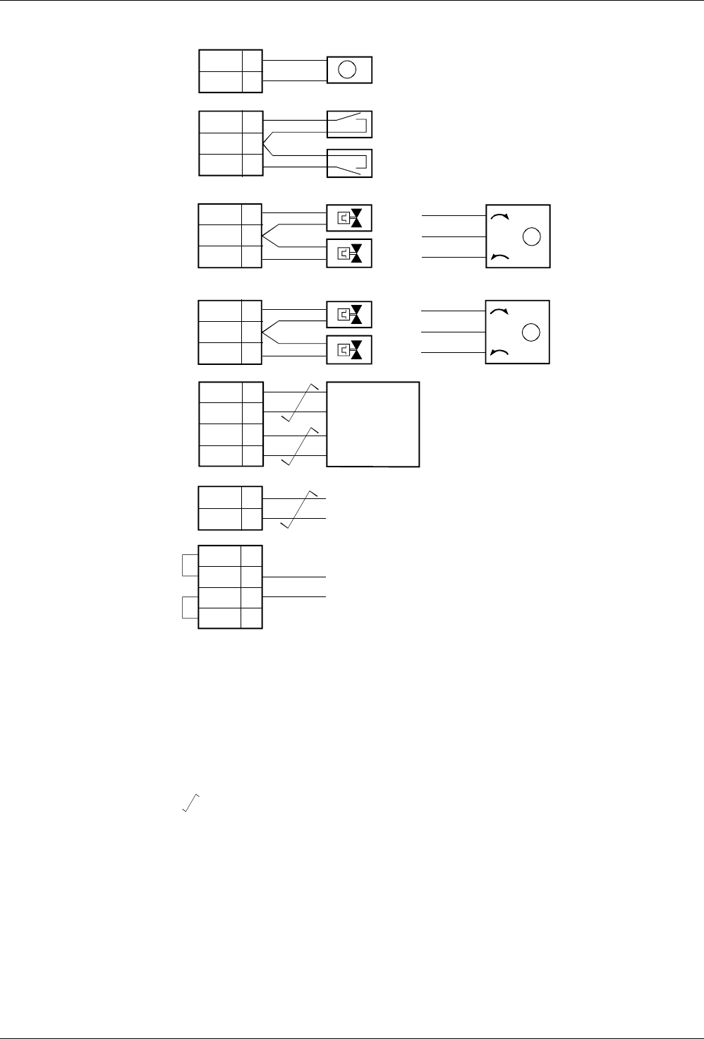
Connection diagrams
1
2
4
5
6
7
8
9
10
11
12
13
14
15
16
17
18
M
D1
GND
D2
Y1
G
Y2
CP –
CP +
B1
Y3
G
Y4
19
19
21
N
L
N
N
L
AC 230 V
KNX / EIB
B2
PPS2
KNX / EIB
Y3
Y4
Y1
Y2
D1
D2
T
B1
GL
Y2.1
M
GL
Y1.1
M
N1
3874A11
21
L
CE –
CE +
CE –
CE +
1
2
4
3
N1 RXB24.1
B1 LG-Ni 1000 temperature sensor
D1, D2 Volt-free contacts (window contact, occupancy sensor, etc.)
Y1...Y4 AC 24 V thermic valve actuators
Y1.1 Motorized AC 24 V, 3-position valve actuator
Y2.1 Motorized AC 24 V, 3-position valve actuator
B2 QAX… room unit
Twisted pair
For information on the compatibility of field devices with the RXB24.1 room
controller, refer to the various application descriptions
(see the CLC and RAD description of functions, document CA110384)
Connection of
field devices, room
unit, KNX / EIB bus
and power supply
Note