3 874 s RXB RXB24.1 Room controller For chilled ceiling and radiator applications CC-02 with Konnex bus communications (S-mode and LTE mode) The RXB24.1 room controller is used for temperature control in individual rooms.
Application The RXB24.1 room controller is optimized for control of chilled ceiling and radiator systems in individual rooms. The application of each controller is determined by the application software. The controllers are delivered with a fixed set of applications, each of which contains various individual applications. The relevant application is selected and activated during commissioning using one of the following tools: • ETS Professional (EIB / KNX Tool Software) • Synco ACS • "HandyTool" (the QAX34.
Types The RXB24.1 room controller has the following outputs: Type AC 24 V triac outputs RXB24.1 For 2 thermic valve actuators or two 3-position actuators RXZ20.1 Accessories: Terminal covers Ordering When ordering please specify the quantity, product name, type code and application group. Example: 30 Room controllers, type RXB24.1/CC-02 Compatibility The RXB24.1 room controller is compatible with field devices from Siemens Building Technologies and with KNX / EIB-compatible third-party devices.
Service LED The programming LED shows the operational status of the room controller as follows: Green flashing Red ON OK, device is in operation • Addressing mode (ACS / ETS) • Fault Parameter download • No supply voltage • Fault • Service LED disabled by software • Start-up (approx. 5.sec) • Fault Orange / green flashing OFF Other patterns Programming pin The programming pin is used to identify the controller in the commissioning phase.
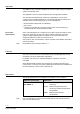
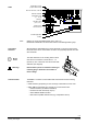
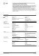
3874Z04 Identification number (unique serial number) Label ID in bar-code form, code 128 Protection standard Temperature range (0 … 50 °C) Serial No. Test date, series (Z, A, B, C…) 010025CA9900 060215B 513 Observe notes in this document Activated application Location Connection terminals Options for use of the labeling fields “Appl.” and “Loc.”: Handwritten identification of the location and the activated application group. All terminals are detachable plug-in screw-terminals.
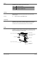
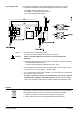
Connecting the tool To facilitate commissioning, the tools ETS Profession or Synco ACS can be connected at three different points (marked (A) in the diagram) in the plant: − to the KNX / EIB bus cable at any point − to the RXB2… controller (RJ45 tool socket) − to the room unit (RJ45 tool socket) A A A A A B B Notes Caution! • The tool socket is a proprietary socket. A Siemens connecting cable must be used (e.g. PXA-C1).
Engineering notes The KNX / EIB Building Services Management Manual and system principles supplement (see "Reference documentation ", page 10) contains the information relevant for the engineering of the KNX / EIB bus (topology, bus repeaters, etc.) and for the selection and dimensions of connecting cables for the supply voltage and field devices. AC 230 V supply cables • The RXB24.1 room controller operates with a mains supply voltage of AC 230 V.
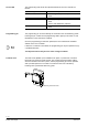
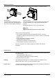
Mounting instructions 3873J07 3873J06 The room controllers can be mounted in any orientation, and fixed as follows: Rail mounting The housing base is designed for snapmounting on DIN rails, type EN50022-35 x 7.5 (can be released with a screwdriver). Surface mounting There are two drill holes for screw-mounting (see “Dimensions” for drilling template). The housing base is fitted with raised supports. Screws: Max. diameter 3.5 mm, min. length 38 mm STOP Note! Tightening torque for fixing screws max. 1.
• In the event of a long-term short circuit (approx. 4 minutes) or overload, the thermal fuse in the transformer may trip. Subsequently, the device must be exchanged. • There is no protection against accidental connection on the AC 24 V side.
Cable connections Connection terminals for signals and power supply (plug-in screw terminals) KNX / EIB bus connection terminals (plug-in screw terminals) Single cable lengths Signal inputs D1, D2 Measured value input B1 AC24 V triac outputs , Y1 … Y4 Interface to room unit Cable type KNX / EIB bus Cable type Tool connecting cable Housing protection standard Protection standard to EN 60529 Protection class Ambient conditions Suitable for use in systems with protection class I or II Normal operation Tem
D2 Y1 G Y2 3874A08 GND 17 18 CE – D1 10 11 12 13 14 15 16 CE + 9 CE – 8 CE + 7 CP + 6 Y4 5 CP – 4 G 3 Y3 2 N.C. 1 B1 RXB24.1 M Connection terminals EIB / KNX T 2 M 1 4 3 QAX... M L L N N AC 230V 19 19 21 21 Measured value input B1 1 Measured value input for LG-Ni 1000 sensors M 2 Measured value input ground Signal inputs D1 4 Signal input GND 5 Signal ground D2 6 Signal input Triac outputs Y1 7 AC 24 V, 0.
Connection diagrams B1 1 M 2 D1 4 GND 5 D2 6 D2 Y1 7 Y1 G 8 Y2 9 Y2 Y3 10 Y3 G 11 Y4 12 T CP + 14 1 CE + 15 4 CE – 16 3 M Y1.1 GL M Y2.1 PPS2 B2 KNX / EIB KNX / EIB N 19 N 19 N L 21 L L 21 N1 GL Y4 2 CE – 18 B1 D1 CP – 13 CE + 17 3874A11 N1 Connection of field devices, room unit, KNX / EIB bus and power supply AC 230 V RXB24.1 B1 LG-Ni 1000 temperature sensor D1, D2 Volt-free contacts (window contact, occupancy sensor, etc.) Y1...
Parallel connection of several thermic valve actuators Up to two thermic actuators per sequence may be connected directly to the room controller. With more than two thermic actuators, a UA1T power amplifier is required. The principle is the same for output Y2. Do not exceed the maximum simultaneous load on outputs Y1 and Y2 (max. 9.5 VA). Power consumption at input X1 of the UA1T: 0.5 VA. Mixed operation: It is not permissible to connect thermic actuators both to the controller and to the power amplifier.
Dimensions 4,4 Dimensions in mm 3,3 35,3 133,2 3873M14 Without terminal cover 3,9 1 62 51,5 5 62 3,9 1 167 35,3 3873M15 With terminal covers 112,4 107,8 14 / 16 Siemens Building Technologies RXB24.
Drilling diagram (1:1) 3873M16 39 78 3,6 43,2 86,3 15 / 16 Siemens Building Technologies RXB24.
Published by: Siemens Switzerland Ltd. Building Technologies Division International Headquarters Gubelstrasse 22 6301 Zug Switzerland Tel. +41 41-724 24 24 www.siemens.com/buildingtechnologies © Siemens Switzerland Ltd 2007 Delivery and technical specifications subject to change 16 / 16 Siemens Building Technologies RXB24.