
Operating Instructions
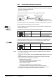
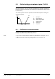
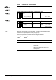
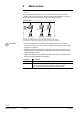
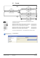
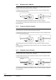
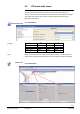
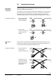
Table Of Contents
- RXB (KNX) applications library
- CLC and RAD description of functions for CC-02
- Table of contents
- 1 Introduction
- 2 Definitions / Tools
- 3 Select communications mode
- 4 Applications / Parameters
- 5 Room operating modes
- 5.1 Description
- 5.2 Overview
- 5.3 Determine the room operating mode with DESIGO (S-mode)
- 5.3.1 Local control of room operating mode via a window contact
- 5.3.2 Central control of room operating mode via input from the Use schedule
- 5.3.3 Central and local control of room operating modebased on occupancy
- 5.3.4 Central control of room operating mode via room operating mode schedule
- 5.3.5 Local control of room operating mode with a room unit
- 5.3.6 Local control of room operating mode via the Temporary Comfort mode input
- 5.3.7 Effective room operating mode
- 5.3.8 DESIGO examples
- 5.4 Determine the room operating mode with third-party products (S-mode)
- 5.4.1 Local control of room operating mode via window contact input
- 5.4.2 Central control of room operating mode with an input from the room operating mode schedule
- 5.4.3 Central control of the room operating mode via the schedules Use and Occupancy
- 5.4.4 Central and local control of room operating mode based on occupancy
- 5.4.5 Local control of room operating mode with a room unit
- 5.4.6 Local control of room operating mode via the Temporary Comfort mode input
- 5.4.7 Effective room operating mode
- 5.4.8 Third-party (S-mode) examples
- 5.5 Determine the room operating mode with Synco (LTE mode)
- 5.5.1 Local control of room operating mode via window contact input
- 5.5.2 Central room operating mode control via Enable Comfort
- 5.5.3 Central control of room operating mode via room operating mode input
- 5.5.4 Local control of room operating mode via presence detector
- 5.5.5 Local control of room operating mode with a room unit
- 5.5.6 LTE mode examples
- 5.6 Determine the room operating mode without a bus (stand-alone)
- 6 Setpoint calculation
- 7 Temperature measurement
- 8 Control sequences
- 9 Master/slave
- 10 General / central functions
- 10.1 Send heartbeat and Receive timeout
- 10.2 Digital inputs
- 10.3 Temporary Comfort mode
- 10.4 Presence detector switch-on and switch-off delay
- 10.5 Heating and cooling demand
- 10.6 Heating/cooling signal output
- 10.7 Special functions
- 10.8 Morning boost (Morning Warmup, 2)
- 10.9 Precooling (Precool, 5)
- 10.10 Test mode (Test, 7)
- 10.11 Emergency heat (8)
- 10.12 Free cooling (Freecool, 10)
- 10.13 Alarm
- 10.14 Reset setpoint shift
- 10.15 Free inputs/outputs
- 10.16 Software version
- 10.17 Device state
- 11 Room unit
- 12 KNX information
- 12.1 Reset and startup response
- 12.2 LED flashing pattern
- 12.3 Startup delay
- 12.4 Bus load
- 12.5 S-mode communication objects for RAD/CLC
- 12.6 LTE-mode communication objects
- 12.7 HandyTool parameters by number
- 12.8 HandyTool parameters, alphabetical
- 12.9 HandyTool enumerations
- 12.10 Data point type description
- 13 FAQ
- 14 Integration of RXB in DESIGO/Synco
- 14.1 Case 1: Integration in Synco
- 14.2 Case 2: Integration in DESIGO
- 14.3 Case 3: Display in DESIGO, with shared Synco schedule
- 14.4 Case 4: Display in DESIGO/Synco, with shared Synco schedule
- 14.5 Case 5: Display in DESIGO, separate schedules
- 14.6 Case 6: Separate display, separate schedules
- 14.7 Case 7: Separate display, shared Synco schedule
- 15 Working with different tools

91/140
Siemens RXB (KNX) Applications library CLC and RAD description of functions for CC-02 CM110384en_04
Building Technologies Control sequences 21 Sep 2010
8.2.6 Central/passive dewpoint monitoring
The dewpoint can be monitored in two ways:
– A dewpoint sensor with a potential-free contact is connected directly to a digital input
of the room controller (see page 102).
–
Dewpoint sensor via bus.
The two inputs are OR-linked: If one is active, dewpoint alarm applies.
RXB... Room controller
EIB / KNX Dewpoint sensor
10384z102en
Room dewpoint alarm input
DI
OR
Room dewpoint alarm output
Since EIB dewpoint sensors are available from a variety of manufacturers, the name of
the EIB output communication object varies accordingly.
The following KNX input communication object is used to integrate a dewpoint sensor
connected to the KNX bus:
Room dewpoint alarm input (input communication object)
Flags
R W C T U
Type Receive timeout States
0 1 1 1 1 1.005
DPT_Alarm
Yes
0 = No alarm
1 = Alarm (condensation)
The dewpoint monitoring status (result of the OR operation) can be evaluated in the
building automation and control system using the following communication object.
Room dewpoint alarm output (output communication object)
Flags
R W C T U
Type Send heartbeat States
1 0 1 1 0 1.005
DPT_Alarm
Yes
0 = No alarm
1 = Alarm (condensation)
For dewpoint monitoring, a logic OR operation is applied to the locally connected
sensor and the bus sensor.
The result is used in the alarm object room dewpoint alarm output on the bus (see
10.13).
When parameterizing, note whether the contacts are NO or NC (see page 102).
Note the following for master/slave configurations:
–
Dewpoint sensor on master:
The sensor is evaluated locally
cooling valve closes.
This information is transmitted to the slaves.
– Dewpoint
sensor on slave:
The sensor is evaluated locally
cooling valve closes.
This information is NOT transmitted to the master and further slaves..
The controller immediately queries the dewpoint alarm input following a reset
(if configured accordingly and provided a dewpoint is integrated).
KNX
R
CO
Notes