
Operating Instructions
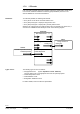
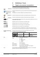
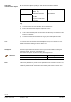
Table Of Contents
- RXB (KNX) applications library
- CLC and RAD description of functions for CC-02
- Table of contents
- 1 Introduction
- 2 Definitions / Tools
- 3 Select communications mode
- 4 Applications / Parameters
- 5 Room operating modes
- 5.1 Description
- 5.2 Overview
- 5.3 Determine the room operating mode with DESIGO (S-mode)
- 5.3.1 Local control of room operating mode via a window contact
- 5.3.2 Central control of room operating mode via input from the Use schedule
- 5.3.3 Central and local control of room operating modebased on occupancy
- 5.3.4 Central control of room operating mode via room operating mode schedule
- 5.3.5 Local control of room operating mode with a room unit
- 5.3.6 Local control of room operating mode via the Temporary Comfort mode input
- 5.3.7 Effective room operating mode
- 5.3.8 DESIGO examples
- 5.4 Determine the room operating mode with third-party products (S-mode)
- 5.4.1 Local control of room operating mode via window contact input
- 5.4.2 Central control of room operating mode with an input from the room operating mode schedule
- 5.4.3 Central control of the room operating mode via the schedules Use and Occupancy
- 5.4.4 Central and local control of room operating mode based on occupancy
- 5.4.5 Local control of room operating mode with a room unit
- 5.4.6 Local control of room operating mode via the Temporary Comfort mode input
- 5.4.7 Effective room operating mode
- 5.4.8 Third-party (S-mode) examples
- 5.5 Determine the room operating mode with Synco (LTE mode)
- 5.5.1 Local control of room operating mode via window contact input
- 5.5.2 Central room operating mode control via Enable Comfort
- 5.5.3 Central control of room operating mode via room operating mode input
- 5.5.4 Local control of room operating mode via presence detector
- 5.5.5 Local control of room operating mode with a room unit
- 5.5.6 LTE mode examples
- 5.6 Determine the room operating mode without a bus (stand-alone)
- 6 Setpoint calculation
- 7 Temperature measurement
- 8 Control sequences
- 9 Master/slave
- 10 General / central functions
- 10.1 Send heartbeat and Receive timeout
- 10.2 Digital inputs
- 10.3 Temporary Comfort mode
- 10.4 Presence detector switch-on and switch-off delay
- 10.5 Heating and cooling demand
- 10.6 Heating/cooling signal output
- 10.7 Special functions
- 10.8 Morning boost (Morning Warmup, 2)
- 10.9 Precooling (Precool, 5)
- 10.10 Test mode (Test, 7)
- 10.11 Emergency heat (8)
- 10.12 Free cooling (Freecool, 10)
- 10.13 Alarm
- 10.14 Reset setpoint shift
- 10.15 Free inputs/outputs
- 10.16 Software version
- 10.17 Device state
- 11 Room unit
- 12 KNX information
- 12.1 Reset and startup response
- 12.2 LED flashing pattern
- 12.3 Startup delay
- 12.4 Bus load
- 12.5 S-mode communication objects for RAD/CLC
- 12.6 LTE-mode communication objects
- 12.7 HandyTool parameters by number
- 12.8 HandyTool parameters, alphabetical
- 12.9 HandyTool enumerations
- 12.10 Data point type description
- 13 FAQ
- 14 Integration of RXB in DESIGO/Synco
- 14.1 Case 1: Integration in Synco
- 14.2 Case 2: Integration in DESIGO
- 14.3 Case 3: Display in DESIGO, with shared Synco schedule
- 14.4 Case 4: Display in DESIGO/Synco, with shared Synco schedule
- 14.5 Case 5: Display in DESIGO, separate schedules
- 14.6 Case 6: Separate display, separate schedules
- 14.7 Case 7: Separate display, shared Synco schedule
- 15 Working with different tools

9/140
Siemens RXB (KNX) Applications library CLC and RAD description of functions for CC-02 CM110384en_04
Building Technologies Definitions / Tools 21 Sep 2010
2 Definitions / Tools
2.1 Signals and parameters (presentation)
Inputs, outputs and parameters of an application can be influenced in various ways.
This description of functions applies the following symbols:
The room unit influences parameters shown with this symbol.
Parameters identified in this way are parameterized using ETS3 Professional (EIB tool
software).
The RXB Konnex controllers CANNOT be parameterized with ETS2.
Parameters identified with this symbol are parameterized with the ACS service tool.
Parameters identified with this symbol are parameterized with the HandyTool.
This indicates inputs and outputs which communicate with other KNX devices. They are
communication objects (CO).
Graphical symbol for an S-mode input communication object.
Graphical symbol for an LTE input communication object.
Graphical symbol for an S-mode output communication object.
Graphical symbol for an LTE output communication object.
The communication objects of the RXB Konnex controllers work in part in S-mode, in
part in LTE mode, and in part in both modes. These objects are described accordingly.
The following table describes each communication object working in S-mode:
Schedule Use (input communication object)
Flags
R W C T U
Type Receive timeout States
0 1 1 0 0 20.002
DPT_BuildingMode
Yes
0 = In use
1 = Not in use
2 = Protection
(1) Communication object name.
Flags: R Read
W Write
C Communication
T Transmit
U Update
Type Konnex data type.
Send heartbeat Yes = Cyclical send.
Receive timeout Yes = Cyclical receive (timeout).
States or values Range of states or values which can be adopted
by the communication object.
A list of all S-mode communication objects is located in section 12.5; see a detailed
description of
the Konnex data types in section 12.10.
Room unit
ETS3 Professional
STOP
Important!
ACS Service
HandyTool
KNX
R
CO
S-mode communication
objects
(1)
Key
Note