
Operating Instructions

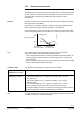
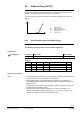
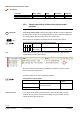
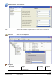
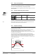
Table Of Contents
- RXB (KNX) applications library
- CLC and RAD description of functions for CC-02
- Table of contents
- 1 Introduction
- 2 Definitions / Tools
- 3 Select communications mode
- 4 Applications / Parameters
- 5 Room operating modes
- 5.1 Description
- 5.2 Overview
- 5.3 Determine the room operating mode with DESIGO (S-mode)
- 5.3.1 Local control of room operating mode via a window contact
- 5.3.2 Central control of room operating mode via input from the Use schedule
- 5.3.3 Central and local control of room operating modebased on occupancy
- 5.3.4 Central control of room operating mode via room operating mode schedule
- 5.3.5 Local control of room operating mode with a room unit
- 5.3.6 Local control of room operating mode via the Temporary Comfort mode input
- 5.3.7 Effective room operating mode
- 5.3.8 DESIGO examples
- 5.4 Determine the room operating mode with third-party products (S-mode)
- 5.4.1 Local control of room operating mode via window contact input
- 5.4.2 Central control of room operating mode with an input from the room operating mode schedule
- 5.4.3 Central control of the room operating mode via the schedules Use and Occupancy
- 5.4.4 Central and local control of room operating mode based on occupancy
- 5.4.5 Local control of room operating mode with a room unit
- 5.4.6 Local control of room operating mode via the Temporary Comfort mode input
- 5.4.7 Effective room operating mode
- 5.4.8 Third-party (S-mode) examples
- 5.5 Determine the room operating mode with Synco (LTE mode)
- 5.5.1 Local control of room operating mode via window contact input
- 5.5.2 Central room operating mode control via Enable Comfort
- 5.5.3 Central control of room operating mode via room operating mode input
- 5.5.4 Local control of room operating mode via presence detector
- 5.5.5 Local control of room operating mode with a room unit
- 5.5.6 LTE mode examples
- 5.6 Determine the room operating mode without a bus (stand-alone)
- 6 Setpoint calculation
- 7 Temperature measurement
- 8 Control sequences
- 9 Master/slave
- 10 General / central functions
- 10.1 Send heartbeat and Receive timeout
- 10.2 Digital inputs
- 10.3 Temporary Comfort mode
- 10.4 Presence detector switch-on and switch-off delay
- 10.5 Heating and cooling demand
- 10.6 Heating/cooling signal output
- 10.7 Special functions
- 10.8 Morning boost (Morning Warmup, 2)
- 10.9 Precooling (Precool, 5)
- 10.10 Test mode (Test, 7)
- 10.11 Emergency heat (8)
- 10.12 Free cooling (Freecool, 10)
- 10.13 Alarm
- 10.14 Reset setpoint shift
- 10.15 Free inputs/outputs
- 10.16 Software version
- 10.17 Device state
- 11 Room unit
- 12 KNX information
- 12.1 Reset and startup response
- 12.2 LED flashing pattern
- 12.3 Startup delay
- 12.4 Bus load
- 12.5 S-mode communication objects for RAD/CLC
- 12.6 LTE-mode communication objects
- 12.7 HandyTool parameters by number
- 12.8 HandyTool parameters, alphabetical
- 12.9 HandyTool enumerations
- 12.10 Data point type description
- 13 FAQ
- 14 Integration of RXB in DESIGO/Synco
- 14.1 Case 1: Integration in Synco
- 14.2 Case 2: Integration in DESIGO
- 14.3 Case 3: Display in DESIGO, with shared Synco schedule
- 14.4 Case 4: Display in DESIGO/Synco, with shared Synco schedule
- 14.5 Case 5: Display in DESIGO, separate schedules
- 14.6 Case 6: Separate display, separate schedules
- 14.7 Case 7: Separate display, shared Synco schedule
- 15 Working with different tools

87/140
Siemens RXB (KNX) Applications library CLC and RAD description of functions for CC-02 CM110384en_04
Building Technologies Control sequences 21 Sep 2010
8.2 Chilled ceiling (CLC01)
The chilled ceiling application has a continuous cooling sequence. The room controllers
operate with a PI algorithm optimized for thermal or motorized valve actuators. (For
simplicity, the diagram below only shows the P-control action.)
The control sequence comes into operation at the effective setpoints for cooling (see
page 67).
100
0
TR [°C]
Y [%]
SpC
YC
C
Y Output signal
TR Room temperature
SpC Effective cooling setpoint
C Cooling sequence
YC Cooling valve
8.2.1 Select actuator types for chilled ceiling
See section 8.1.1, page 79 on selecting actuator types for radiators.
The following information differs from the radiator applications:
HandyTool
Parameter Short name Basic setting
*051 Actuat c’surf valve STA71
Settings
STE71 1 SSA81 10 Motoric bus 250
STA71 3 SSB81 11 El’mech 3
rd
party devices 252
STP71 4 SQS81 12 Thermal 3
rd
party devices 253
STA72E 5 SSC81 13 Motoric 3
rd
party devices 254
STP72E 6 SSP81 14
If thermal actuators are selected, Y3 / Y4 are always controlled in parallel to ensure
that several actuators can be connected at the same time.
Exact parallel operation of several thermal valve actuators is not guaranteed. If
several radiators are controlled by the same controller, motorized actuators are the
preferred device.
If nevertheless thermal actuators are controlled in parallel, "3rd Party Thermic" must
be parameterized regardless of make.
Thermal actuators work at higher temperatures. To ensure a fast reaction, the
actuators are slightly preheated continuously (5% – 1 sec ON / 19 sec OFF). Then
thus also receive pulses from the controller when closed.
Actuator type
Thermal valve actuators
Notes