
Operating Instructions

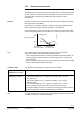
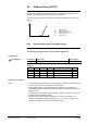
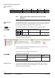
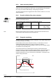
Table Of Contents
- RXB (KNX) applications library
- CLC and RAD description of functions for CC-02
- Table of contents
- 1 Introduction
- 2 Definitions / Tools
- 3 Select communications mode
- 4 Applications / Parameters
- 5 Room operating modes
- 5.1 Description
- 5.2 Overview
- 5.3 Determine the room operating mode with DESIGO (S-mode)
- 5.3.1 Local control of room operating mode via a window contact
- 5.3.2 Central control of room operating mode via input from the Use schedule
- 5.3.3 Central and local control of room operating modebased on occupancy
- 5.3.4 Central control of room operating mode via room operating mode schedule
- 5.3.5 Local control of room operating mode with a room unit
- 5.3.6 Local control of room operating mode via the Temporary Comfort mode input
- 5.3.7 Effective room operating mode
- 5.3.8 DESIGO examples
- 5.4 Determine the room operating mode with third-party products (S-mode)
- 5.4.1 Local control of room operating mode via window contact input
- 5.4.2 Central control of room operating mode with an input from the room operating mode schedule
- 5.4.3 Central control of the room operating mode via the schedules Use and Occupancy
- 5.4.4 Central and local control of room operating mode based on occupancy
- 5.4.5 Local control of room operating mode with a room unit
- 5.4.6 Local control of room operating mode via the Temporary Comfort mode input
- 5.4.7 Effective room operating mode
- 5.4.8 Third-party (S-mode) examples
- 5.5 Determine the room operating mode with Synco (LTE mode)
- 5.5.1 Local control of room operating mode via window contact input
- 5.5.2 Central room operating mode control via Enable Comfort
- 5.5.3 Central control of room operating mode via room operating mode input
- 5.5.4 Local control of room operating mode via presence detector
- 5.5.5 Local control of room operating mode with a room unit
- 5.5.6 LTE mode examples
- 5.6 Determine the room operating mode without a bus (stand-alone)
- 6 Setpoint calculation
- 7 Temperature measurement
- 8 Control sequences
- 9 Master/slave
- 10 General / central functions
- 10.1 Send heartbeat and Receive timeout
- 10.2 Digital inputs
- 10.3 Temporary Comfort mode
- 10.4 Presence detector switch-on and switch-off delay
- 10.5 Heating and cooling demand
- 10.6 Heating/cooling signal output
- 10.7 Special functions
- 10.8 Morning boost (Morning Warmup, 2)
- 10.9 Precooling (Precool, 5)
- 10.10 Test mode (Test, 7)
- 10.11 Emergency heat (8)
- 10.12 Free cooling (Freecool, 10)
- 10.13 Alarm
- 10.14 Reset setpoint shift
- 10.15 Free inputs/outputs
- 10.16 Software version
- 10.17 Device state
- 11 Room unit
- 12 KNX information
- 12.1 Reset and startup response
- 12.2 LED flashing pattern
- 12.3 Startup delay
- 12.4 Bus load
- 12.5 S-mode communication objects for RAD/CLC
- 12.6 LTE-mode communication objects
- 12.7 HandyTool parameters by number
- 12.8 HandyTool parameters, alphabetical
- 12.9 HandyTool enumerations
- 12.10 Data point type description
- 13 FAQ
- 14 Integration of RXB in DESIGO/Synco
- 14.1 Case 1: Integration in Synco
- 14.2 Case 2: Integration in DESIGO
- 14.3 Case 3: Display in DESIGO, with shared Synco schedule
- 14.4 Case 4: Display in DESIGO/Synco, with shared Synco schedule
- 14.5 Case 5: Display in DESIGO, separate schedules
- 14.6 Case 6: Separate display, separate schedules
- 14.7 Case 7: Separate display, shared Synco schedule
- 15 Working with different tools

85/140
Siemens RXB (KNX) Applications library CLC and RAD description of functions for CC-02 CM110384en_04
Building Technologies Control sequences 21 Sep 2010
8.1.5 Downdraft compensation
This function is only active in Comfort mode.
In situations where (owing to large internal heat gains) there is no heating demand from
the room despite a low outdoor temperature (supplied via bus), large window surfaces
can impair indoor comfort (through radiated cold, downward flow of cold air,
condensation).
A radiator located under the window can be used to slow the downward flow of cold air
and compensate for cold radiation.
To achieve this, the radiator is switched on whenever the outdoor temperature drops
below a predefined value (the outside temperature 0% valve position).
The maximum heating output (set under
Max. valve position) is reached at the coldest
outdoor temperature (which can be set under
Max. outdoor temperature valve position).
25%
100%
0%
T
OA
Heating output
Outdoor temp.
max. valve position
Max. valve position
10385D17en_01
Outdoor temp.
0% valve position
Thermic
Motoric
The controller adds the values representing the valve position for downdraft
compensation and the valve position for the heating sequence.
– If the room temperature rises as a result of the downdraft compensation feature, the
heating sequence reduces the opening of the associated valve, so correcting the
room temperature.
– When the sequence reaches zero, the room temperature is increased by the residual
heat from the downdraft compensation feature.
The heat output calculated by the controller is achieved as follows:
LTHW radiators with
motorized valve actuators
The valve is opened to the heat output value [%].
LTHW radiators with
thermal valve actuators
The minimum heat output is 25% (LED08: 10%):
400 seconds "OPEN" (1s On, 1 s Off) 1200 s "CLOSE" (1s On, 19 s Off)
Heat output 50%:
400 seconds "OPEN" (1s On, 1 s Off) 400 s "CLOSE" (1s On, 19 s Off)
Heat output 80%:
1600 seconds "OPEN" (1s On, 1 s Off) 400 s "CLOSE" (1s On, 19 s Off)
The long cycle time ensures that the valves are fully opened and closed.
In a network containing several room controllers, the opening of the Siemens thermic
actuators is staggered to prevent the heating load from fluctuating.
If a thermal radiator valve actuator and a thermal heating/cooling valve actuator work
in parallel, the controller controls them alternately.
Function
Note
Controller output
Note